Auxiliary device and method for composite material interface shear strength test device
A technology for interfacial shear strength and composite materials, applied in measuring devices, using stable tension/pressure to test material strength, analyzing materials, etc., can solve problems such as difficult to accurately measure interfacial shear strength of composite materials
- Summary
- Abstract
- Description
- Claims
- Application Information
AI Technical Summary
Problems solved by technology
Method used
Image
Examples
Embodiment 1
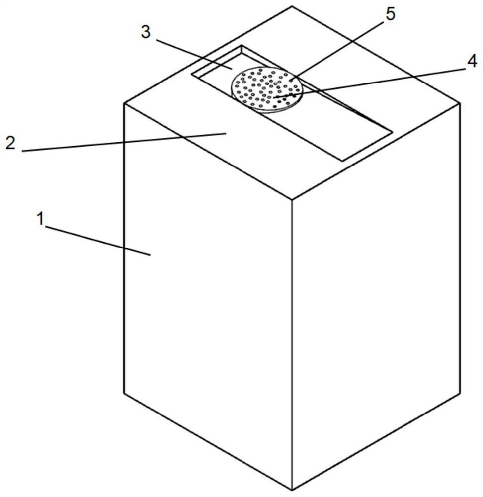
[0050] Such as Figure 1-7 As shown, an auxiliary device of a composite material interface shear strength test device includes a polishing device 1, a column stand 7 and an observation fixture 13, wherein:
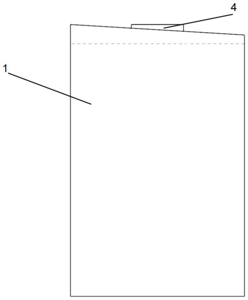
[0051] The top surface of the polishing device 1 is a polishing device slope 2 with an inclination angle of θ, and a polishing device horizontal rectangular groove 3 is provided along the inclination direction of the polishing device slope 2,
[0052] The top surface of the pedestal 7 is provided with a pedestal rectangular chute 8 with an inclination angle of θ, and a fiber push-out groove 9 is provided along the inclination direction of the pedestal rectangular chute 8,
[0053] The top surface of the observation fixture 13 is provided with an observation fixture rectangular chute 14 with an inclination angle of θ,
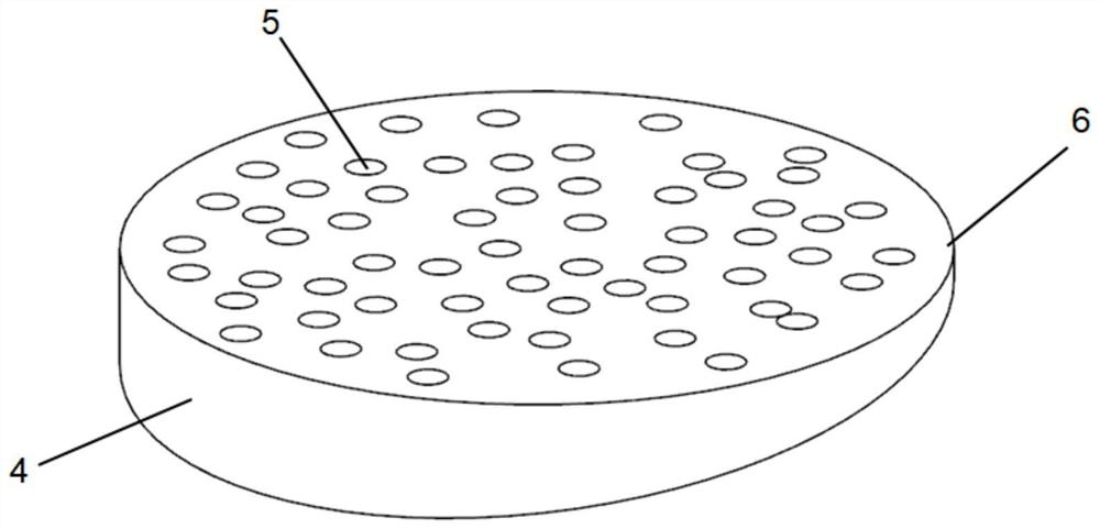
[0054] The composite material test sample 4 is placed in the horizontal rectangular groove 3 of the polishing device, and the top surface of the composite ...
Embodiment 2
[0060] A method for an auxiliary device of a composite material interface shear strength testing device, comprising the following steps:
[0061] S1. Make a composite material test sample with a thickness of 1-2 mm, use liquid glue to fix the composite material test sample on the horizontal rectangular groove of the polishing device, and use sandpaper for polishing to make one end surface of the composite material test sample flat , the other end surface is polished to be an inclined surface consistent with the inclination angle θ of the inclined surface of the polishing device. After the preparation is completed, the composite material test sample is removed with glue cleaning agent, and put into acetone for degumming and cleaning. After the composite material test sample is aired After drying, use a vernier caliper to measure the thickness L of the thin end face of the composite material test sample;
[0062] S2. Use a cotton swab to apply a little liquid glue on both sides ...
Embodiment 3
[0072] In this embodiment 3, the composite material test sample 4 is a SiCf / Ti metal matrix composite material, the material of the polishing device 1 is stainless steel, and the material of the column platform 7 and the observation fixture 13 is aluminum alloy; The inclination angle of the inclined plane 2 of the device, the inclination angle of the rectangular chute 8 of the column base and the inclination angle θ of the rectangular chute 14 of the observation and fixing device are the same, all of which are 3 to 5°. The test method specifically includes the following steps:
[0073] (1), such as Figure 1-2 As shown, the SiCf / Ti metal matrix composite material is pasted in the horizontal rectangular groove 3 of the polishing device on the slope 2 of the polishing device with PT-02 adhesive, and the SiCf / Ti metal matrix composite material is polished to a surface of 3~ 5° slope, use acetone to clean and remove the polished SiCf / Ti metal matrix composite material, and use a v...
PUM
| Property | Measurement | Unit |
|---|---|---|
| thickness | aaaaa | aaaaa |
Abstract
Description
Claims
Application Information
 - R&D
- Intellectual Property
- Life Sciences
- Materials
- Tech Scout
- Unparalleled Data Quality
- Higher Quality Content
- 60% Fewer Hallucinations
Browse by: Latest US Patents, China's latest patents, Technical Efficacy Thesaurus, Application Domain, Technology Topic, Popular Technical Reports.
© 2025 PatSnap. All rights reserved.Legal|Privacy policy|Modern Slavery Act Transparency Statement|Sitemap|About US| Contact US: help@patsnap.com


