Display panel and display device

A technology of display panel and display area, applied in static indicators, instruments, diodes, etc., can solve the problem of serious light diffraction in the light-transmitting area, and achieve the effect of improving the imaging effect and reducing the degree of light diffraction.

Active Publication Date: 2020-05-22
WUHAN TIANMA MICRO ELECTRONICS CO LTD
View PDF9 Cites 16 Cited by
  • Summary
  • Abstract
  • Description
  • Claims
  • Application Information

AI Technical Summary

Problems solved by technology

In order to increase the screen-to-body ratio and realize functions such as front camera at the same time, a technology of setting an under-screen shooting area in the screen display area has emerged. In addition to setting the light-emitting device for realizing the display function, the under-screen shooting area can also be set The light-transmitting area, the front camera can realize the front-facing shooting function through the light-transmitting area in the shooting area under the screen. However, in the current front-facing shooting area, the light diffraction phenomenon in the light-transmitting area is more serious

Method used


Image

  • Display panel and display device
  • Display panel and display device
  • Display panel and display device

Examples


Embodiment Construction

[0030] In order to make the purpose, technical solutions and advantages of the embodiments of the present application clearer, the technical solutions in the embodiments of the present application will be clearly and completely described below in conjunction with the drawings in the embodiments of the present application.

[0031] Terms used in the embodiments of the present application are only for the purpose of describing specific embodiments, and are not intended to limit the present application. The singular forms "a", "said" and "the" used in the embodiments of this application and the appended claims are also intended to include plural forms unless the context clearly indicates otherwise.

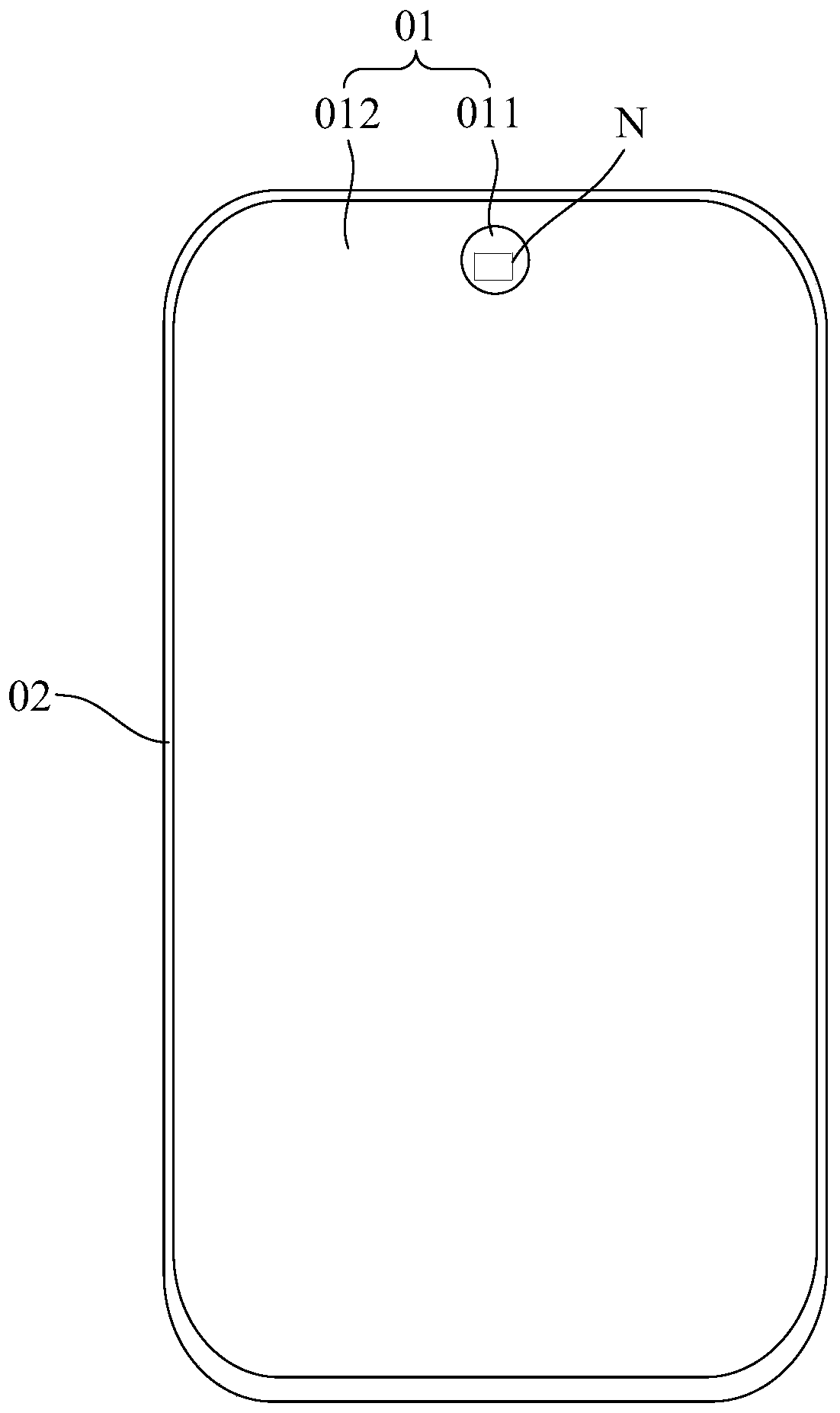
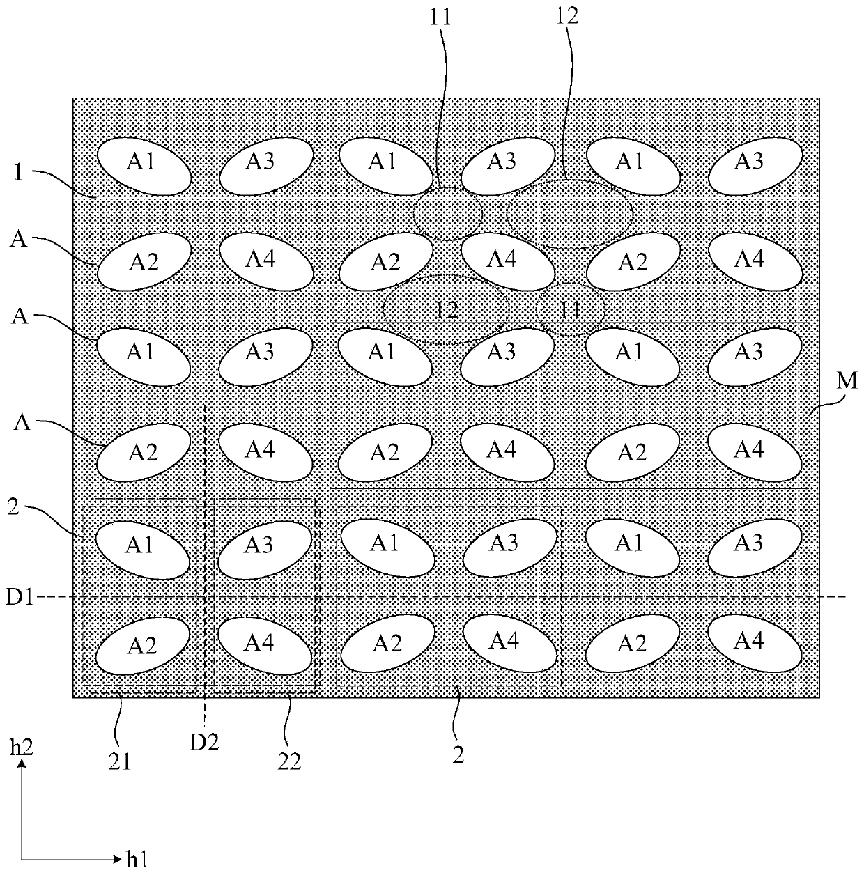
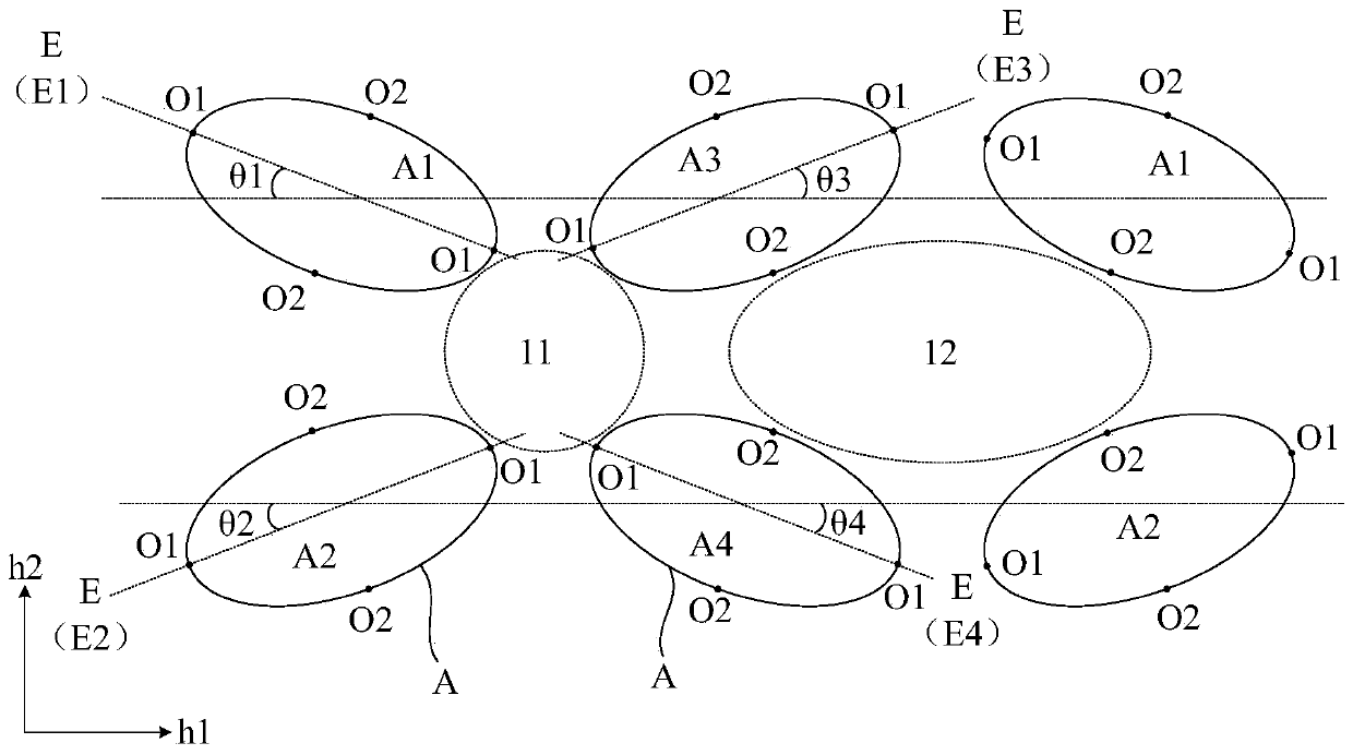
[0032] Such as figure 1 , figure 2 and image 3 as shown, figure 1 is a top view of a display panel in an embodiment of the present application, figure 2 for figure 1 The local enlarged schematic diagram of the N region in the middle, image 3 for figure 2 The partially enl...


PUM

PropertyMeasurementUnit
lengthaaaaaaaaaa

Abstract

The embodiment of the invention provides a display panel and a display device, relates to the technical field of display, and can reduce the light diffraction degree of a light transmission area. Thedisplay panel comprises a display area, the display area comprises an optical component setting area, the optical component setting area comprises a shading area and a plurality of light-transmittingarea units distributed in rows and columns, and each light-transmitting area unit comprises a plurality of light-transmitting areas; each light-transmitting area unit comprises a first light-transmitting area group and a second light-transmitting area group which are arranged along a first direction, each first light-transmitting area group comprises a first light-transmitting area and a second light-transmitting area which are arranged along a second direction, and each second light-transmitting area group comprises a third light-transmitting area and a fourth light-transmitting area which are arranged along the second direction; each light-transmitting area has a length direction, and an included angle between the length direction of each light-transmitting area and the first direction ranges from 10 degrees to 40 degrees and comprises an endpoint value; and, in the light-transmitting area unit, the length direction of each light-transmitting area points to the area among the first light-transmitting area, the second light-transmitting area, the third light-transmitting area and the fourth light-transmitting area.

Description

technical field [0001] The present application relates to the field of display technology, in particular to a display panel and a display device. Background technique [0002] At present, the design of electronic devices such as mobile phones and tablet computers is developing towards a high screen-to-body ratio. The screen-to-body ratio is used to represent the relative ratio between the screen and the front panel area of ​​the electronic device. Problems to be solved by people. In order to increase the screen-to-body ratio and realize functions such as front camera at the same time, a technology of setting an under-screen shooting area in the screen display area has emerged. In addition to setting the light-emitting device for realizing the display function, the under-screen shooting area can also be set In the light transmission area, the front camera can realize the front shooting function through the light transmission area in the shooting area under the screen. Howeve...

Claims


Application Information

Patent Timeline
Patent Type & Authority Applications(China)
IPC IPC(8): H01L51/52H01L27/32G09G3/3208
CPCG09G3/3208H10K59/35H10K59/12H10K50/858H10K50/86H10K59/353H10K59/65H10K59/126H10K59/131H10K50/865
Inventor 吴风云马扬昭
Owner WUHAN TIANMA MICRO ELECTRONICS CO LTD
Why Eureka
Try Eureka