Display panel and manufacturing method thereof

A display panel and manufacturing method technology, applied in the direction of diodes, semiconductor devices, electrical components, etc., can solve problems such as difficult full-screen display, achieve the effects of improving display quality, avoiding diffraction, and improving imaging quality

Pending Publication Date: 2021-11-02
KUNSHAN GO VISIONOX OPTO ELECTRONICS CO LTD
View PDF0 Cites 3 Cited by
  • Summary
  • Abstract
  • Description
  • Claims
  • Application Information

AI Technical Summary

Problems solved by technology

[0003] Taking a mobile phone as an example, because the front of the mobile phone needs to place components such as a camera and a light sensor, the existing solution is generally to design a non-display area on the top of the screen, such as the "notch screen" and "water drop screen" that are widely used now. solution, but it is difficult to achieve the effect of a real full-screen display
[0004] At present, in order to increase the screen-to-body ratio and realize functions such as front camera at the same time, there is a technology of setting the shooting area under the screen in the display area of ​​the screen. In addition to setting the pixel unit for realizing the display function, the shooting area under the screen can also be There is a light transmission area, and the front camera can realize the front shooting function through the light transmission area in the shooting area under the screen. However, in the current front shooting area, the light diffraction phenomenon in the light transmission area is relatively serious

Method used


Image

  • Display panel and manufacturing method thereof
  • Display panel and manufacturing method thereof
  • Display panel and manufacturing method thereof

Examples


Embodiment Construction

[0035] In order to make the object, technical solution and advantages of the present invention clearer, the present invention will be further described in detail below in conjunction with the embodiments and accompanying drawings. It should be understood that the specific embodiments described here are only used to explain the present invention, not to limit the present invention.

[0036] In the description of the present invention, it should be noted that the terms "center", "upper", "lower", "left", "right", "vertical", "horizontal", "inner", "outer" etc. The indicated orientation or positional relationship is based on the orientation or positional relationship shown in the drawings, and is only for the convenience of describing the present invention and simplifying the description, rather than indicating or implying that the referred device or element must have a specific orientation, or in a specific orientation. construction and operation, therefore, should not be constr...


PUM


Abstract

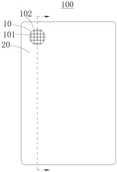
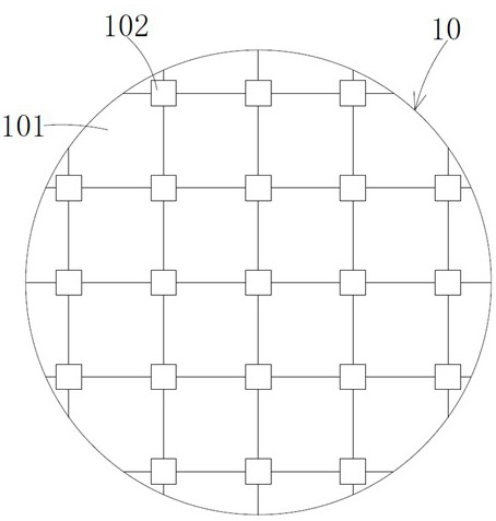
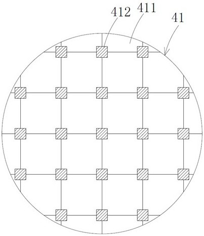
The invention provides a display panel and a manufacturing method thereof. The display panel comprises a first display area and a second display area adjacent to the first display area, wherein the light transmittance of the first display area is greater than that of the second display area, the first display area comprises a plurality of light-transmitting areas and a plurality of first pixel unit setting areas, and the plurality of first pixel unit setting areas comprise a plurality of first pixel units. The display panel further comprises: a substrate; and a light shielding layer, which comprises a first light shielding part, wherein the first light shielding part is arranged on the sides, close to the substrate, of the multiple first pixel units, the first light shielding part comprises multiple first light shielding patterns, and orthographic projections of the multiple first light shielding patterns on a substrate body coincide with orthographic projections of the multiple first pixel units on the substrate body. According to the invention, the multiple first shading patterns can effectively avoid diffraction in a light transmission process, lower the light diffraction degree in the light transmitting areas, and improve the imaging quality of a sensor in the first display area.

Description

technical field [0001] The invention belongs to the field of display technology, in particular to a display panel and a manufacturing method thereof. Background technique [0002] With the development of mobile phones and other consumer electronics products including display panels and cameras, people's requirements for these products are not limited to functionality, but also turn to design, artistry and good visual experience, such as high Full screens with a screen-to-body ratio are becoming more and more popular. The so-called screen-to-body ratio is the ratio of the screen area to the overall machine area. A higher screen-to-body ratio can bring users a better visual experience. [0003] Taking a mobile phone as an example, because the front of the mobile phone needs to place components such as a camera and a light sensor, the existing solution is generally to design a non-display area on the top of the screen, such as the "notch screen" and "water drop screen" that ar...

Claims


Application Information

Patent Timeline
Patent Type & Authority Applications(China)
IPC IPC(8): H01L27/32
CPCH10K59/60H10K59/65H10K59/12H10K59/126H10K59/1201
Inventor 许传志谢正芳
Owner KUNSHAN GO VISIONOX OPTO ELECTRONICS CO LTD
Why Eureka
Try Eureka