
Display device

a technology of display device and display plate, which is applied in the direction of instrumentation, planar/plate-like light guide, transportation and packaging, etc., can solve the problem of reducing visibility and achieve the effect of appropriate visibility

Active Publication Date: 2018-05-29
YAZAKI CORP
View PDF13 Cites 6 Cited by
  • Summary
  • Abstract
  • Description
  • Claims
  • Application Information

AI Technical Summary

Benefits of technology

The present invention provides a display device with good visibility. To achieve this, the display device has two display surfaces, one for emitting light and displaying an image, and another placed on top of the first surface. The second display surface has grooves created on it that form a drawing pattern. These grooves are parallel to the first display surface and the exit surface of light from the second display surface. The grooves also prevent diffracted light from forming an image on the first display surface. By doing this, the display device ensures that the image is visible without being obstructed by other light reflections. This results in a better display that is easier to see.

Problems solved by technology

Thus, there is a possibility of reducing the visibility.

Method used


Image

  • Display device
  • Display device
  • Display device

Examples


embodiment

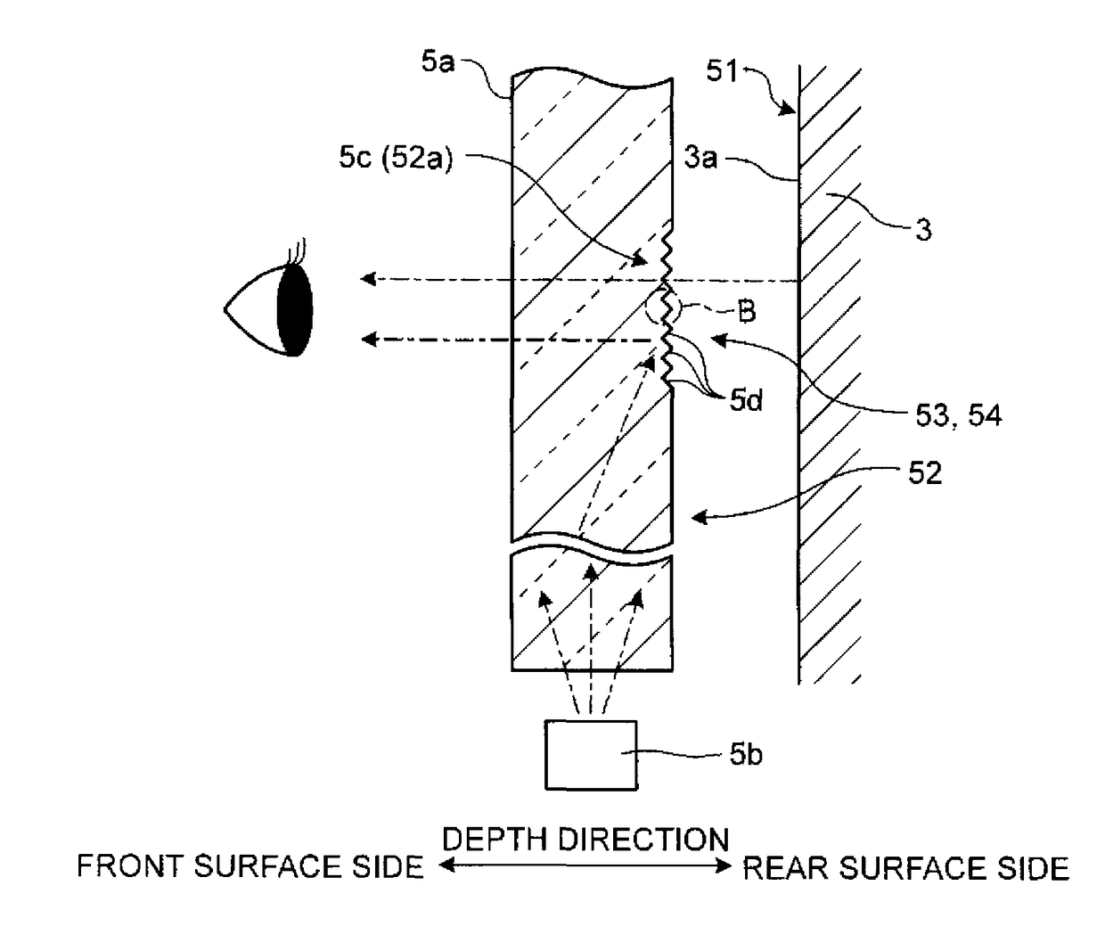
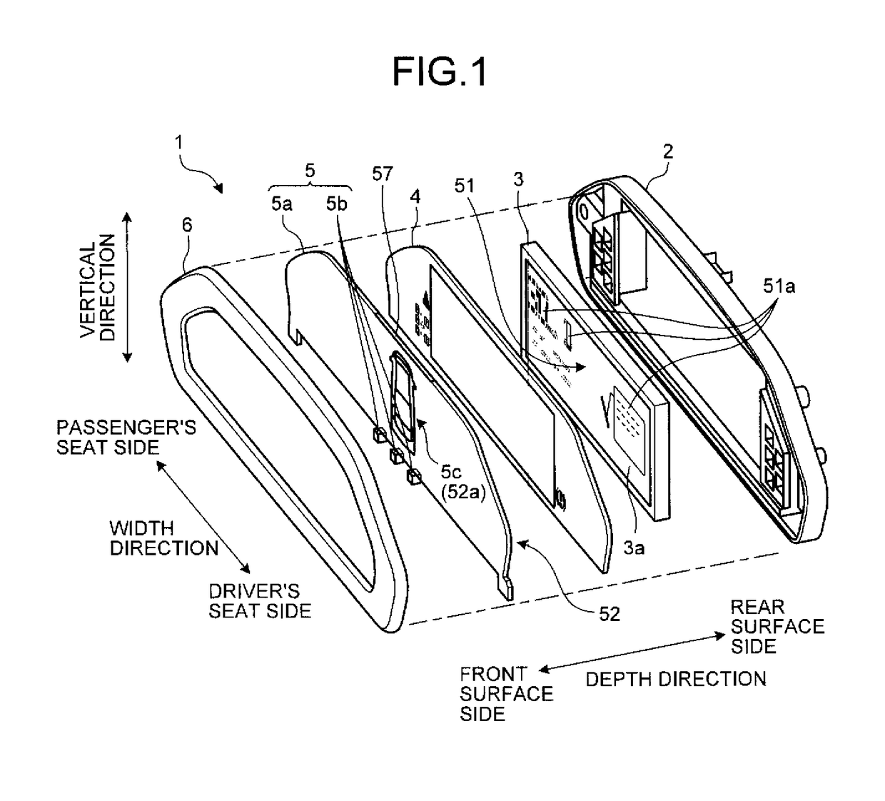
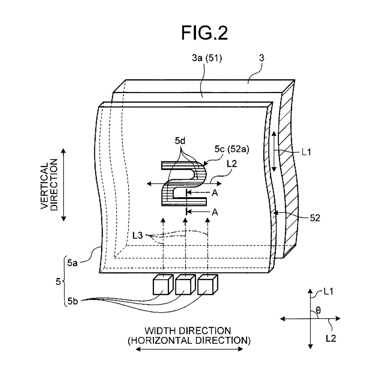
[0028]FIG. 1 is an exploded perspective view schematically illustrating a configuration of a display device according to an embodiment. FIG. 2 is a perspective view schematically illustrating a configuration of a superimposing display device in the display device according to the embodiment. FIG. 3 is a schematic sectional view cut along line A-A in FIG. 2. FIG. 4 is a partial sectional view inside an enclosure line B in FIG. 3. FIG. 5, FIG. 6, and FIG. 7 are schematic views for explaining the prerequisites of a luminance measurement test of the display device. FIG. 8 is a diagrammatic view illustrating results of the luminance measurement test of the display device. FIG. 9 is a schematic view for explaining a principle of generating a virtual image in the display device according to a comparative example. FIG. 10 is a schematic view for explaining a groove pitch in the display device according to the embodiment. FIG. 11 is a schematic view for explaining a principle of preventing a...


PUM


Abstract

A display device includes a first display surface that emits light and displays vehicle information, and a second display surface that is placed on the first display surface in an overlapping manner, transmits the light emitted from the first display surface, and on which grooves that form a drawing pattern are created, wherein the grooves with a groove pitch are created so as to prevent diffracted light having visible light range components that is emitted from the first display surface and that is diffracted by the grooves from forming an image in an eye range determined in advance according to a vehicle.

Description

CROSS-REFERENCE TO RELATED APPLICATION(S)[0001]The present application claims priority to and incorporates by reference the entire contents of Japanese Patent Application No. 2015-111245 filed in Japan on Jun. 1, 2015.BACKGROUND OF THE INVENTION1. Field of the Invention[0002]The present invention relates to a display device.2. Description of the Related Art[0003]As a conventional display device mounted on a vehicle and the like, for example, Japanese Patent Application Laid-open No. 2012-32286 discloses a display device that includes a first display unit that displays instruments of a vehicle and a second display unit that displays additional information. The second display unit of the display device is provided with a plurality of colorless and transparent light guide plates arranged on top of the front side of a scale plate of the first display unit in an overlapping manner, and a drawing pattern is formed on the light guide plates by a groove.[0004]In such a display device, for e...

Claims


Application Information

Patent Timeline
Patent Type & Authority Patents(United States)
IPC IPC(8): B60Q1/00F21V8/00B60Q1/26
CPCG02B6/006G02B6/0036B60Q1/26
Inventor FUJITA, SUNAO
Owner YAZAKI CORP
Learn More