Direct wave cavitation suppressor for focused shock-wave devices

a technology of focused shock wave and suppressor, which is applied in the field of shockwave focusing devices, can solve the problems of preexisting bubbles on and near the target, reducing reducing the effectiveness so as to reduce the effect of premature bubble growth, and reduce the efficiency of focused shock wav

Inactive Publication Date: 2006-04-25
UNIV OF WASHINGTON
View PDF3 Cites 5 Cited by
  • Summary
  • Abstract
  • Description
  • Claims
  • Application Information

AI Technical Summary

Benefits of technology

[0007]The invention includes the discovery that the effectiveness of focused shock-waves is decreased by direct waves emanating from the shock-wave generator. The shock-waves diverge spherically from the shock-wave generator. Those shock-waves that strike the focusing reflector are focused by the reflector to form the focused shock-wave that is then directed to a target, e.g. a kidney stone. The direct waves are those shock-waves that miss the reflector and move directly to the target. It has been observed that direct waves cause a premature growth of preexisting bubbles on and near the target. These bubbles can act as a protective membrane around the region of target, decreasing the efficiency of the focused shock-wave. It has been discovered, by removing or decreasing the effect of the direct wave, premature bubble growth is reduced.
[0008]The present invention is basically characterized by providing a direct-wave cavitation suppressor and positioning it between the first and second foci of the focusing reflector, in a position to block direct shock-waves from traveling from the shock-wave generator directly to the second foci. The direct-wave cavitation suppressor has a periphery spaced inwardly from the focusing reflector. The outer periphery is shaped to substantially prevent diffraction enhancement of the direct waves as it moves around the direct-wave cavitation suppressor.
[0010]Another aspect of the invention is to provide a method of producing a focused shock-wave and delivering it to an object. This method is basically characterized by providing a shock-wave generator and a focusing reflector positioned to direct a focused shock wave on an object. A direct-wave cavitation suppressor is positioned between the generator and object in a position to block direct waves from traveling directly from the generator to the object. The shock-wave generator is operated to discharge shock-wave creating energy outwardly from itself. The focusing reflector is used to receive shock-wave energy and focus it and direct it as a focused wave on the object. The direct-wave cavitation suppressor is configured to substantially block the direct shock waves from traveling directly to the object. The direct-wave cavitation suppressor is also configured to prevent diffraction enhancement of the direct waves as they move around the direct-wave cavitation suppressor. In preferred form, the direct-wave cavitation suppressor is generally in the shape of a disk having an irregular periphery. In one form, the focusing reflector is shaped substantially like an end portion of an ellipse. An electrical spark discharge device or an electromagnetic generator is used for the shock-wave generator.

Problems solved by technology

It has been observed that direct waves cause a premature growth of preexisting bubbles on and near the target.
These bubbles can act as a protective membrane around the region of target, decreasing the efficiency of the focused shock-wave.

Method used


Image

  • Direct wave cavitation suppressor for focused shock-wave devices
  • Direct wave cavitation suppressor for focused shock-wave devices
  • Direct wave cavitation suppressor for focused shock-wave devices

Examples


Embodiment Construction

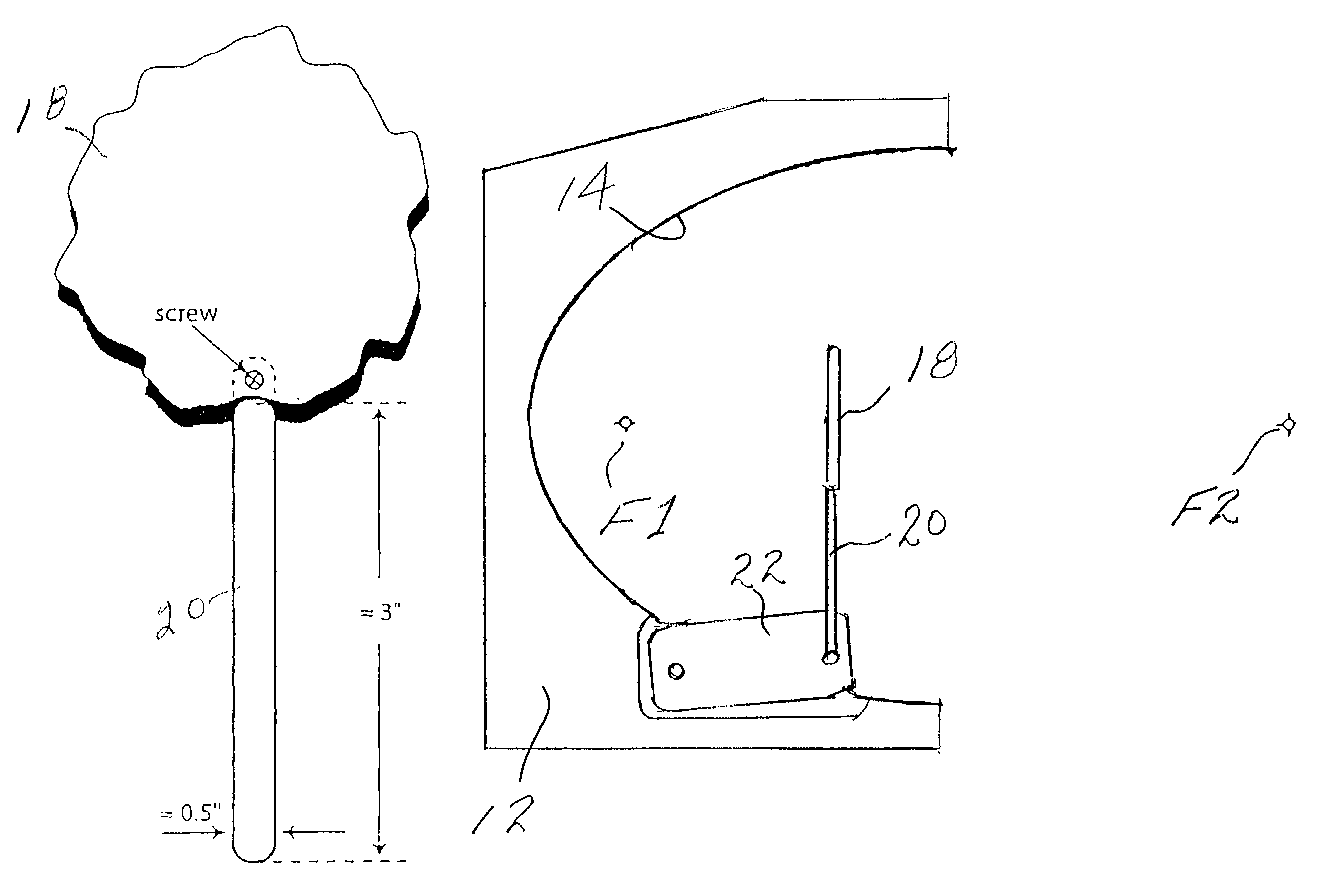
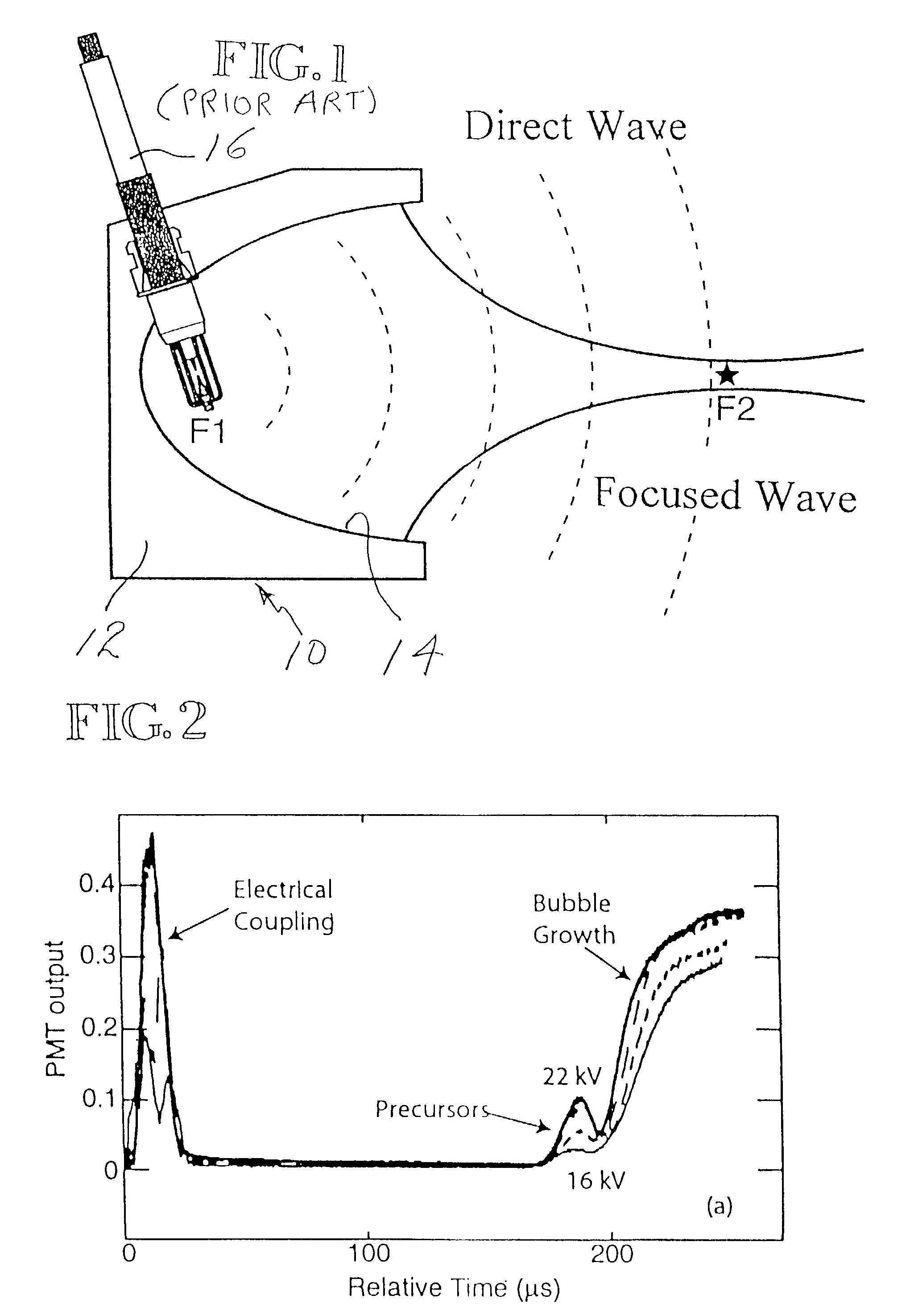
[0030]FIG. 1 is a schematic diagram of a prior art lithotripter 10. It comprises a body 12 formed to provide a focusing reflector 14 and mounts a spark discharge device 16. The focusing surface 14 is an end portion of an ellipsoid or has a curvature that will perform substantially like an elliptical reflector. For background purposes, FIG. 9 is a diagram of a true ellipse. By definition, an ellipse is the locus of a point the sum of whose undirected distances from two fixed points equals a constant. The two fixed points are the foci F (−c, 0) and F (c, 0). The midpoint of the segment joining the foci is the center and the line through them is the principal axis of the ellipse. The distance F (−c, 0) P (x, y) added to the distance P (x, y) F (c, 0) is a constant for all points P (x, y) on the ellipse. The important feature of the ellipse to the present invention is that if the ellipse is three-dimensional, viz. ellipsoidal, energy extending from F (−c, 0) to P (x, y) would be reflect...


PUM


Abstract

A reflector (14) reflects energy emitting from an energy source (16) and focuses and directs it to a target. An aperture stop or suppressor disk (18) is positioned between the energy source (16) and target. The outer periphery of the aperture stop or suppressor disk (18) is an irregular curve (FIGS. 12 and 13). This shape of the periphery prevents diffraction enhancement to the direct wave.

Description

[0001]The subject invention was made under DARPA contract no. N00014-99-1-0793, managed by ONR, and developed under NIH grant P01 DK 43881-09.TECHNICAL FIELD[0002]This invention relates to shock-wave focusing devices, e.g. electrohydraulic and electromagnetic lithotripters. More particularly, it relates to a method and apparatus for making the focused shock-wave more efficient, enabling it to perform its function in a shorter period of time.BACKGROUND OF THE INVENTION[0003]Shock-wave devices are commonly used clinically for therapeutic treatment. For example, an electrohydraulic shock-wave lithotripter is a device that generates a focused shock-wave and directs it onto a clinical target, such as a kidney stone. An electrohydraulic shock-wave lithotripter is only one example of the shock-wave devices that can benefit from the present invention. This device is characterized by a focusing reflector having spaced-apart first and second foci. A shock-wave generator is positioned substant...

Claims


Application Information

Patent Timeline
Patent Type & Authority Patents(United States)
IPC IPC(8): A61B17/22
CPCA61B17/225A61B2017/22027
Inventor MATULA, THOMAS J.HILMO, PAULBAILEY, MICHAEL
Owner UNIV OF WASHINGTON
Why Eureka
Try Eureka