Micro-vibration long-distance real time image detecting system based on image surface digital holography

A digital holography and micro-vibration technology, applied to measuring devices, measuring ultrasonic/sonic/infrasonic waves, instruments, etc., can solve the problems of inability to detect irregular vibrations in real time, low shooting speed of photoelectric imaging devices, complex demodulation calculation process, etc. problem, to achieve the effect of remote detection of surface vibration, real-time detection of vibration, and avoidance of diffraction calculation process

Inactive Publication Date: 2015-04-22
BEIHANG UNIV
View PDF4 Cites 7 Cited by
  • Summary
  • Abstract
  • Description
  • Claims
  • Application Information

AI Technical Summary

Problems solved by technology

[0005] The problems existing in the system using this kind of method are: ①The photoelectric imaging device used has a low shooting speed, so it can only detect vibrations with a frequency below 100Hz, and at the same time, it cannot detect irregular vibrations in real time, which cannot meet practical applications needs
②The holographic interference image generally formed by this type of system is formed by the interference of the scattered light diffraction image on the vibrating surface of the object and the reference light. During the demodulation calculation process, it needs to go through a relatively complicated diffraction holographic reproduction calculation, which leads to complex demodulation calculation process and difficult calculation. Due to problems such as slow speed, it is impossible to realize real-time vibration detection above 300Hz
③ The scattered light received by this type of system on the vibrating surface of the measured object rapidly attenuates as the distance increases, and it is impossible to achieve long-distance vibration detection of more than 1 meter

Method used


Image

  • Micro-vibration long-distance real time image detecting system based on image surface digital holography
  • Micro-vibration long-distance real time image detecting system based on image surface digital holography

Examples


Embodiment Construction

[0030] The present invention will be further described in detail below in conjunction with the accompanying drawings.

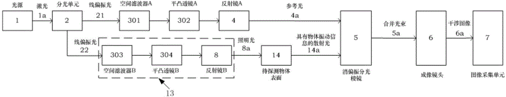
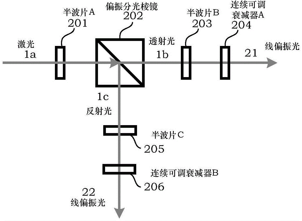
[0031] Such as figure 1 , figure 2 As shown, the present invention is a micro-vibration remote real-time surface detection system based on digital holography of the image surface. Reflecting mirror A4, reflecting mirror B8, depolarizing beam splitting prism 5, imaging lens 6 and image acquisition unit 7.

[0032]The light splitting unit 2 receives the laser light emitted by the light source 1, and outputs linearly polarized light A21 and linearly polarized light B22; the linearly polarized light A21 passes through the spatial filter A301, the plano-convex lens A302, and the mirror A4 in sequence, and then enters the depolarization beam splitter 5 The linearly polarized light B22 is incident on the depolarization beam splitter 5 after passing through the spatial filter B303, the plano-convex lens B304, the mirror B8, and the surface 14 of the object to be d...


PUM


Abstract

The invention discloses a micro-vibration long-distance real time image detecting system based on image surface digital holography. Received laser is divided into two beams of linear polarized light by a light split unit, and then the two beams of the linear polarized light are input in two spatial filters; one beam of the linear polarized light sequentially passes through a planoconvex lens and a reflector, and then the beam of the linear polarized light is seemed as reference light passes into a dispolarization splitting prism; the other beam of the linear polarized light sequentially passes through a planoconvex lens and a reflector and turns into illumination light. The illumination light irradiates the outer surface of an object which is to be detected, passes into the dispolarization splitting prism after scattering, and is output into an image collecting device through an imaging lens. Using a high-speed CMOS camera, digital hologram can be continuously shot at a high-speed. The detection range of the vibration frequency of the device can be improved, and multi-position micro-vibration long-distance real time detection in a certain area of the outer surface of the object can be achieved.

Description

technical field [0001] The present invention relates to a micro-vibration detection system, more particularly, to a micro-vibration remote real-time surface detection device and imaging vibration demodulation algorithm based on image plane digital holography. Background technique [0002] The non-contact micro-vibration detection system with optical technology can be divided into two types: point detection and surface detection according to the detection area. The point detection technology represented by optical triangulation method and laser Doppler method has the advantages of high detection accuracy and good real-time performance. However, there are two main problems with them: one is to treat the area irradiated by the laser as a point and detect its overall vibration, which cannot subdivide the vibration of smaller parts in the area, that is, it cannot realize multi-point vibration in the area. Synchronous real-time detection (surface detection); second, it is necessa...

Claims


Application Information

Patent Timeline
Patent Type & Authority Applications(China)
IPC IPC(8): G01H9/00
Inventor 肖文丛琳潘锋陈宗晖张兆海
Owner BEIHANG UNIV
Why Eureka
Try Eureka