
Lighting circuit compatible with high-power emergency driving and having emergency dimming function

A lighting circuit and high-power technology, which is applied in the field of emergency lighting, can solve the problems that ordinary drivers cannot be directly connected to the AC input terminal, difficult to transform, unacceptable, etc., to prolong the emergency lighting time, reduce the cost of emergency lighting, and low power output Effect

Pending Publication Date: 2020-05-22
SUZHOU CYANTRONIC TECH CO LTD
View PDF0 Cites 1 Cited by
  • Summary
  • Abstract
  • Description
  • Claims
  • Application Information

AI Technical Summary

Problems solved by technology

[0002] At present, most of the emergency drivers in the market are directly connected to the load (shared with the common lighting driver). Ordinary drivers cannot be directly connected to the AC input. If the AC input of the ordinary driver is connected, the battery will be quite large and the cost Can't stand it, basically can't accept it
Or it is a special emergency drive for emergency lamps, but it can only be used for emergency and cannot be used for lighting. The disadvantage of this is that it is very inconvenient to install. To modify the existing lamps, it is necessary to increase the interface, which is very difficult to transform and brings troubles to users. great inconvenience

Method used


Image

  • Lighting circuit compatible with high-power emergency driving and having emergency dimming function
  • Lighting circuit compatible with high-power emergency driving and having emergency dimming function
  • Lighting circuit compatible with high-power emergency driving and having emergency dimming function

Examples


Embodiment Construction

[0028] In order to enable those skilled in the art to better understand the solutions of the present invention, the technical solutions in the embodiments of the present invention will be clearly and completely described below in conjunction with the drawings in the embodiments of the present invention. Obviously, the described embodiments are only It is an embodiment of a part of the present invention, but not all embodiments. Based on the embodiments of the present invention, all other embodiments obtained by persons of ordinary skill in the art without making creative efforts shall fall within the protection scope of the present invention.

[0029] It should be noted that the terms "first" and "second" in the description and claims of the present invention and the above drawings are used to distinguish similar objects, but not necessarily used to describe a specific sequence or sequence. It is to be understood that the data so used are interchangeable under appropriate circ...


PUM


Abstract

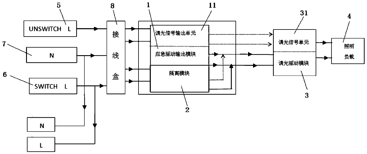
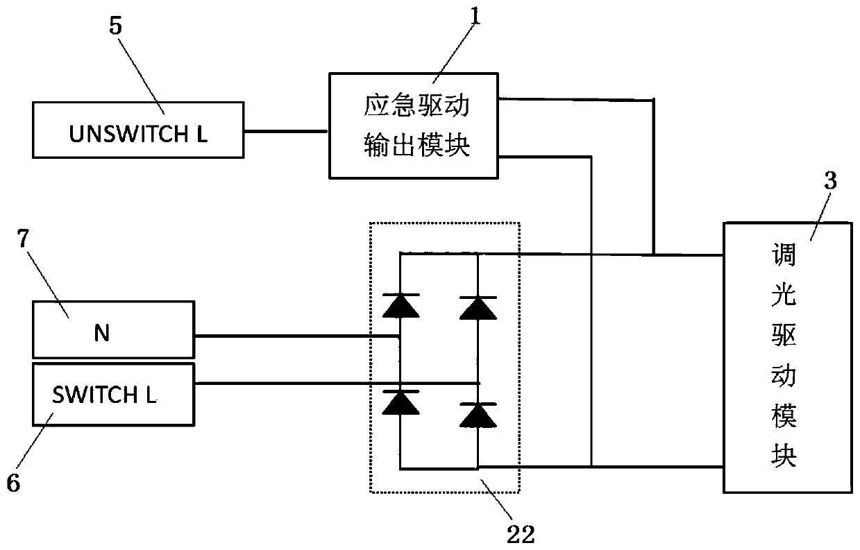
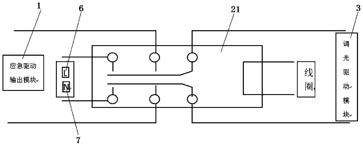
The invention discloses a lighting circuit compatible with high-power emergency driving and having an emergency dimming function. The lighting circuit comprises an emergency power supply line, an emergency driving module, a common lighting power supply line and a dimming driving module; the emergency driving module comprises an emergency driving output module with a dimming signal output unit andan isolation module, and the dimming driving module comprises a dimming signal unit; the common lighting power supply circuit is connected with the dimming driving module, and the dimming driving module is connected with the lighting load; the emergency power supply line is connected with the emergency driving output module, the emergency driving output module is connected with the dimming drivingmodule, and the isolation module is used for isolating the emergency driving module from the common lighting power supply line; and the dimming signal output unit is used for sending a dimming instruction to the dimming signal unit, and the dimming signal unit is used for dimming the lighting load according to the dimming instruction. According to the invention, the dimming interface on a commondriver is utilized, and only the emergency driving output module is used for sending a low-power dimming instruction to the dimming interface, so that dimming can be carried out in an emergency lighting state.

Description

technical field [0001] The invention relates to the field of emergency lighting, in particular to a lighting circuit compatible with high-power emergency drive and having an emergency dimming function. Background technique [0002] At present, most of the emergency drivers in the market are directly connected to the load (shared with the common lighting driver). Ordinary drivers cannot be directly connected to the AC input. If the AC input of the ordinary driver is connected, the battery will be quite large and the cost I can't stand it, basically it's unacceptable. Or it is a special emergency drive for emergency lamps, but it can only be used for emergency and cannot be used for lighting. The disadvantage of this is that it is very inconvenient to install. To modify the existing lamps, it is necessary to increase the interface, which is very difficult to transform and brings troubles to users. Great inconvenience. Contents of the invention [0003] In order to solve th...

Claims


Application Information

Patent Timeline
Patent Type & Authority Applications(China)
IPC IPC(8): H05B47/10
Inventor 曹东明匡文韬
Owner SUZHOU CYANTRONIC TECH CO LTD
Learn More