Horizontal bar with protective effect for physical exercise
A technology for physical exercise and horizontal bar, applied in horizontal bars, gymnastics equipment, sports accessories, etc., can solve the problems of peeling paint on horizontal bars, peeling off protective paint, failure of the third backing plate, etc., achieving the effect of convenient operation and avoiding erosion
- Summary
- Abstract
- Description
- Claims
- Application Information
AI Technical Summary
Problems solved by technology
Method used
Image

Examples
Embodiment 1
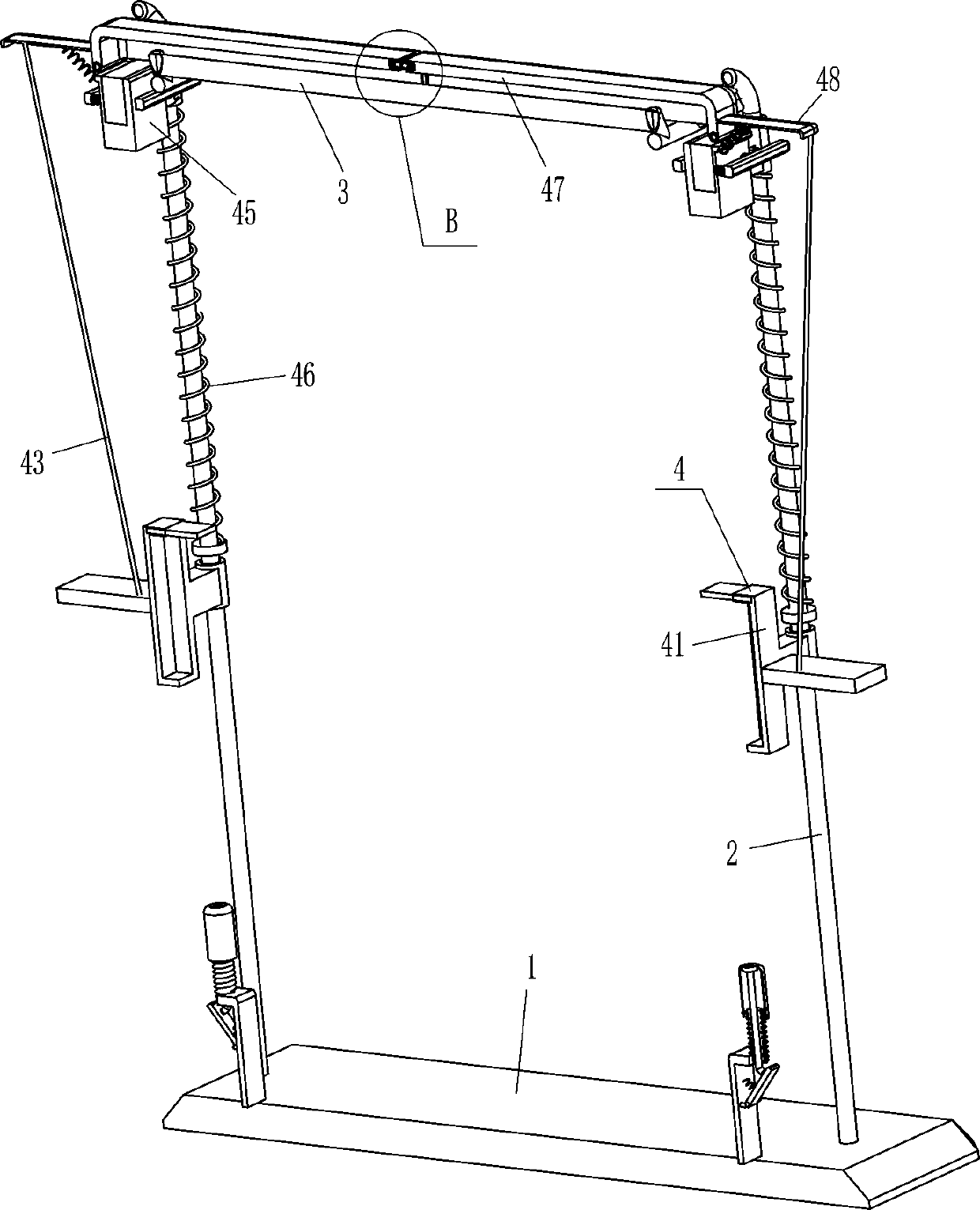
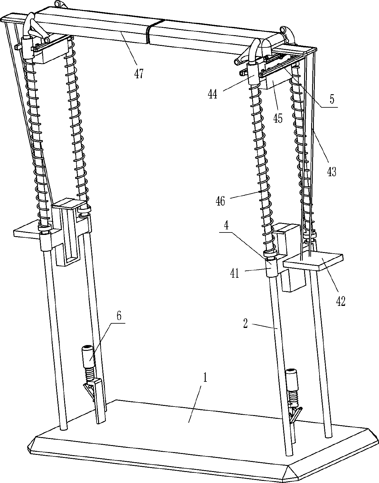
[0024] see Figure 1-Figure 3 , a horizontal bar for physical exercise with a protective effect, comprising a base 1, a support rod 2, a horizontal bar 3, a protective mechanism 4 and a clamping mechanism 5, and the left and right sides of the top of the base 1 are symmetrically fixedly connected with two supports Rod 2, four support rods 2 tops are fixedly connected with a horizontal bar 3, between the two support rods 2 on the left and between the two support rods 2 on the right are provided with a protective mechanism 4, and the protective mechanism 4 is provided with a card. Tight mechanism5.
[0025] Protective mechanism 4 comprises driving slotted plate 41, fixed plate 42, backguy 43, sliding sleeve 44, movable block 45, first spring 46, protective frame 47, connecting plate 48 and second spring 49, the sliding type on support bar 2 A sliding sleeve 44 is provided, a first spring 46 is wound between the bottom of the sliding sleeve 44 and the middle part of the support ...
Embodiment 2
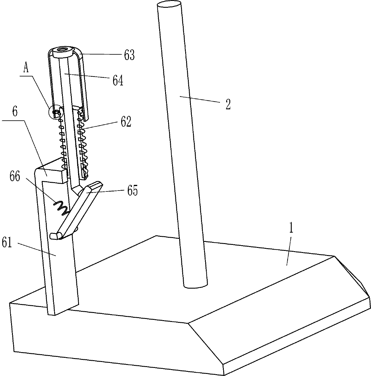
[0031] see figure 1 , figure 2 , Figure 4 and Figure 5 Compared with Embodiment 1, the main difference of this embodiment is that in this embodiment, a locking mechanism 6 is also included, and the locking mechanism 6 includes an L-shaped plate 61, a threaded rod 62, a sleeve 63, a sliding rod 64, a limiter Position plate 65, the fourth spring 66 and one-way swing block 67, the middle part of the left and right sides of the top of base 1 is fixedly connected with L-shaped plate 61, and L-shaped plate 61 is located between the support rods 2 on the left and right sides, and the outside of L-shaped plate 61 The end is fixedly connected with a threaded rod 62, and the middle part of the threaded rod 62 is slidingly provided with a sliding rod 64, and the top of the sliding rod 64 is connected with a sleeve 63 in a rotating manner, and the sleeve 63 cooperates with the driving groove plate 41, and the inner surface of the sleeve 63 There are three one-way swing blocks 67 eve...
Embodiment 3
[0034] see figure 2 and Figure 6 The main difference between this embodiment and embodiment 1 and embodiment 2 is that in this embodiment, a sealing block 8, a strong magnet 9 and a fifth spring 10 are also included, and the inner ends of the protective frames 47 on the left and right sides are all provided with concave holes. Groove 7, the sliding type in the groove 7 is provided with sealing block 8, the inner side of sealing block 8 is evenly spaced and fixedly connected with strong magnet 9, the strong magnets 9 on the left and right sides cooperate with each other, the left side of the left sealing block 8 and the left side Fifth springs 10 are evenly spaced between the inner surfaces of the groove 7 , and fifth springs 10 are also evenly spaced between the right side of the right sealing block 8 and the inner surface of the right groove 7 .
[0035] Initially, the fifth spring 10 is in a stretched state. When the protective frame 47 swings outward, the outward swing o...
PUM
 Abstract
Description
Claims
Application Information
 - R&D
- Intellectual Property
- Life Sciences
- Materials
- Tech Scout
- Unparalleled Data Quality
- Higher Quality Content
- 60% Fewer Hallucinations
Browse by: Latest US Patents, China's latest patents, Technical Efficacy Thesaurus, Application Domain, Technology Topic, Popular Technical Reports.
© 2025 PatSnap. All rights reserved.Legal|Privacy policy|Modern Slavery Act Transparency Statement|Sitemap|About US| Contact US: help@patsnap.com