An automatic riveting machine used for lamp head assembly rivet conveying and correction

A rivet machine and rivet technology, applied in the field of rivet machines, can solve the problems of reduced operating efficiency, rivets are prone to material jams, and increased lamp head defective products, etc., to achieve the effect of improving verticality

Active Publication Date: 2021-12-07
芜湖邦为诺能源科技有限公司
View PDF12 Cites 0 Cited by
  • Summary
  • Abstract
  • Description
  • Claims
  • Application Information

AI Technical Summary

Problems solved by technology

[0004] The existing technology can only assemble one lamp cap at a time, and the efficiency is low. When conveying rivets, it is easy to push and stack in batches, and the defective products of the assembled lamp caps increase; Rivets with small tracks are prone to skewing, and rivets larger than the conveying track are prone to material jams. Once material jams occur, the equipment needs to stop running to sort out the jammed materials before running, which reduces operating efficiency.

Method used


Image

  • An automatic riveting machine used for lamp head assembly rivet conveying and correction
  • An automatic riveting machine used for lamp head assembly rivet conveying and correction
  • An automatic riveting machine used for lamp head assembly rivet conveying and correction

Examples


Embodiment 1

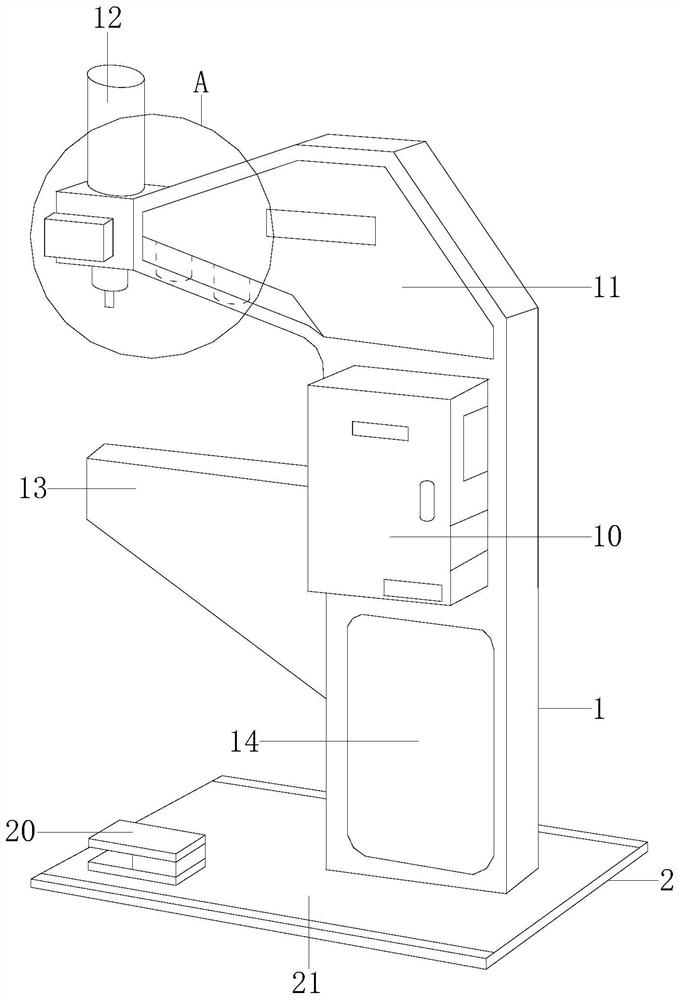
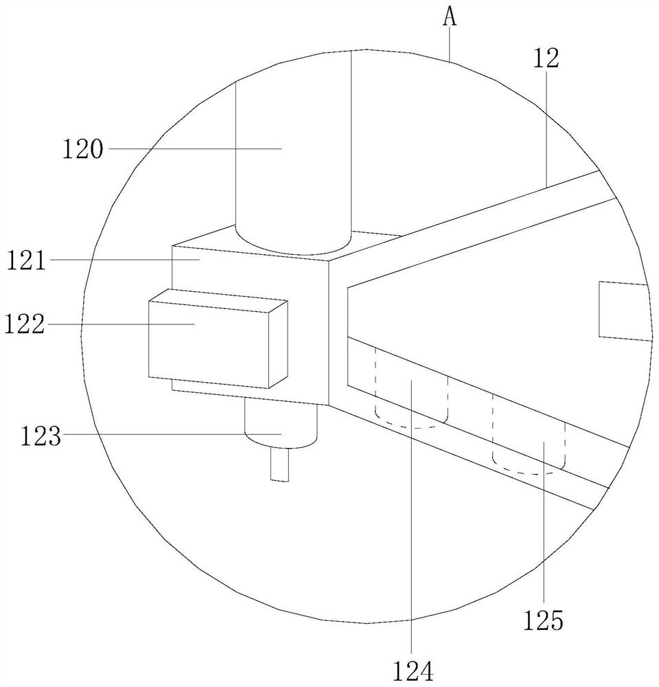
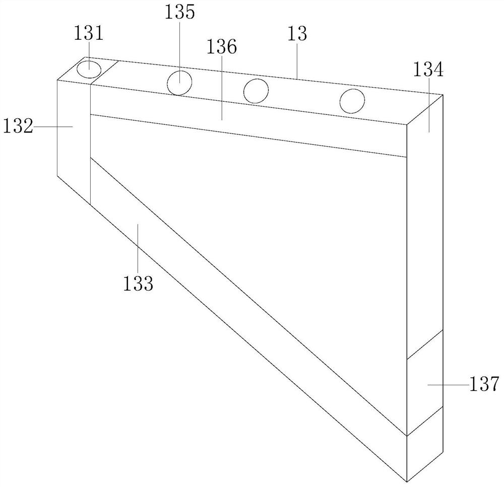
[0031] Example 1 see Figure 1-7, the present invention provides a technical scheme of automatic riveting machine for rivet assembly and correction of lamp caps: its structure includes a nail pressing machine 1 and a base 2, the nail pressing machine 1 is welded to the base 2, and the nail pressing machine 1 is controlled by Box 10, rivet stand 11, rivet press head 12, rivet seat 13, machine door 14, described control box 10 is locked with rivet stand 11, and described rivet press head 12 is installed on the rivet stand 11, and described rivet stand 11 It is assembled and connected with the rivet seat 13. The base 2 is composed of a pedal 20 and a seat plate 21. The pedal 20 and the locking seat plate 21 are connected by bolts. The rivet press head 12 includes a press head motor 120, a mounting frame 121, a press Head control board 122, main pressure head 123, one-position auxiliary pressure head 124, two-position auxiliary pressure head 125, the main pressure head 123, one-po...

Embodiment 2

[0033] Example 2 see Figure 8-11 , the present invention provides a technical scheme of an automatic rivet machine for conveying and correcting lamp cap assembly rivets: its structure is an automatic rivet machine for lamp cap assembly rivet conveying and correcting according to claim 1, characterized in that: the feeding The side rail 1331 includes buckle circle 400, miniature rail frame 401, and welding rail 402. The feeding side rail 1331 and the two-position rail plate 302 not only play a role in stable transportation, but also assist in lifting and adjusting the height of rivet transportation, further improving For the stability of rivet delivery, the buckle circle 400 is buckled with the miniature rail frame 401, the micro rail frame 401 is welded with the welding rail 402, and the two-position rail plate 302 includes a miniature horizontal rail 3021 and a spliced ​​inlay circle 3022. The miniature horizontal rail 3021 is locked with the splicing inlay circle 3022, and ...


PUM


Abstract

The invention discloses an automatic rivet machine for conveying and correcting rivets in lamp head assembly. The structure includes a nail press machine and a base, and the nail press machine is welded to the base. The nail press machine consists of a control box, a rivet frame, a rivet press head, and a rivet seat. , the machine door, the control box is locked with the rivet frame, the rivet head is installed on the rivet frame, the rivet frame is assembled and connected with the rivet seat, the base is composed of a pedal and a seat plate, and the rivet of the present invention is transported from the machine door to the rivet head below At the rivet seat, the feeding device realizes the orderly delivery of rivets at intervals during the conveying process, avoiding the phenomenon of pushing and stacking during batch conveying. The indenter and the two-position auxiliary indenter realize rapid and continuous assembly. Facing rivets of different sizes, the two-position rail plate and the feeding side rail cooperate with the transmission to realize height adjustment. Stable operation and high efficiency.

Description

technical field [0001] The invention relates to the field of riveting machines, in particular to an automatic riveting machine used for conveying and correcting lamp head assembly rivets. Background technique [0002] The rivet machine is mainly used for the connection of accessories. The rivet is squeezed and deformed by a momentary high-pressure force to fix the accessories. Handbags, shoes, hats, hardware, and other industries will use the rivet machine; [0003] When assembling the lamp caps in the lighting industry, the lamp caps will be fixed to the rivet machine pressure port one by one, and then the rivets will be transported to the pressure port for high-pressure assembly. [0004] The existing technology can only assemble one lamp cap at a time, and the efficiency is low. When conveying rivets, it is easy to push and stack in batches, and the defective products of the assembled lamp caps increase; Rivets with small tracks are prone to skewing, and rivets with larg...

Claims


Application Information

Patent Timeline
Patent Type & Authority Patents(China)
IPC IPC(8): B21J15/14B21J15/32
CPCB21J15/14B21J15/32
Inventor 孙玉荣
Owner 芜湖邦为诺能源科技有限公司
Why Eureka
Try Eureka