
Synchronous fastening device

A technology for fastening devices and fasteners, which is applied in the direction of portable motorized devices, wrenches, motor tools, etc., can solve the problems of high environmental index requirements, complex structure composition, and cumbersome motion relations, etc., and achieve simple and tight transmission of motion relations. High solid efficiency and the effect of improving work efficiency

Active Publication Date: 2022-02-01
BEIJING U PRECISION TECH
View PDF5 Cites 0 Cited by
  • Summary
  • Abstract
  • Description
  • Claims
  • Application Information

AI Technical Summary

Problems solved by technology

The existing above-mentioned devices and equipment have complex structures, cumbersome motion relations, low reliability, high requirements on environmental indicators, and are expensive

Method used


Image

  • Synchronous fastening device
  • Synchronous fastening device
  • Synchronous fastening device

Examples


Embodiment 2

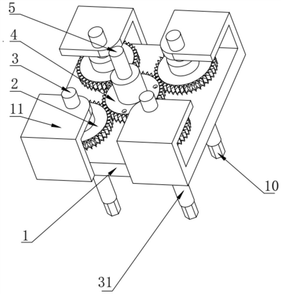
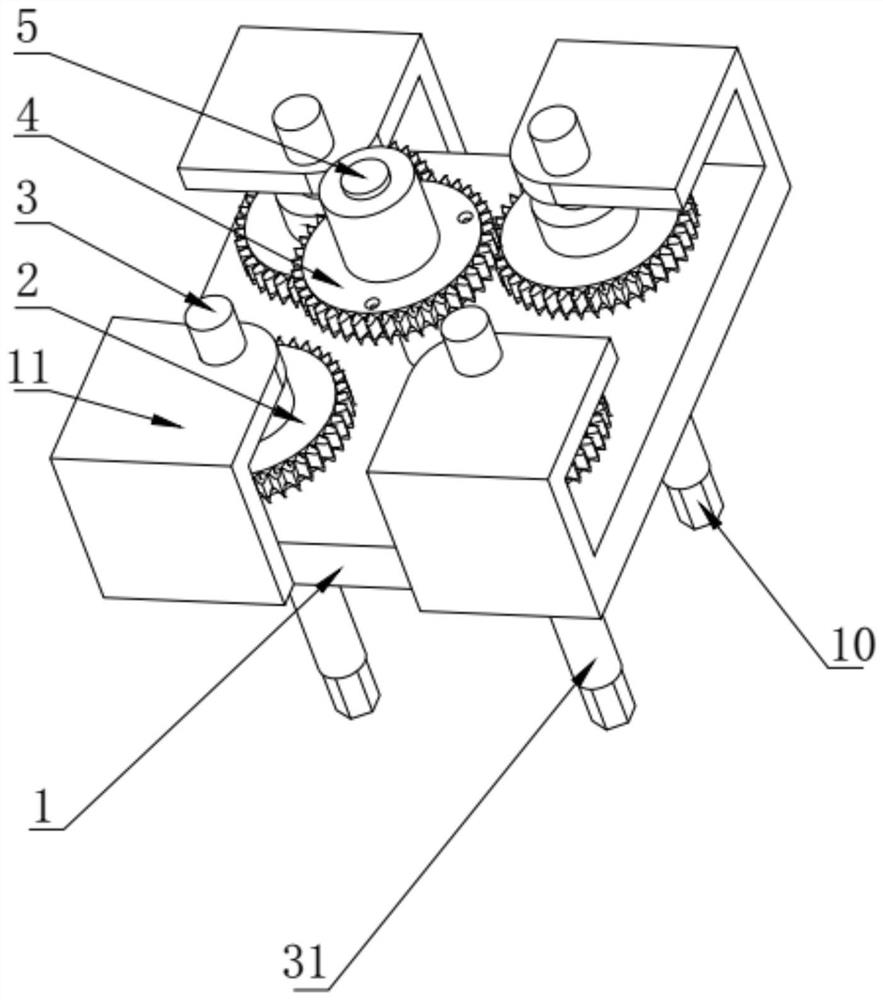
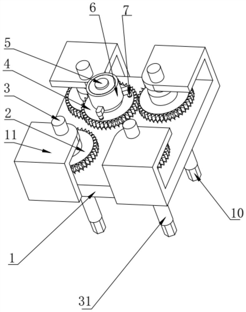
[0059] The structural difference between this embodiment and Embodiment 1 is that the axes of the driving gear 4 and the driven gear 2 are parallel to each other and staggered in the axial direction. When the driving gear 4 moves toward the driven gear 2, one of the situations is The gap between the teeth of the driving gear 4 just coincides with the teeth of the driven gear 2, and the driving gear 4 and the driven gear 2 can enter into normal meshing without any rotation; in another case, the driving gear 4 and the driven gear 2 When the centerlines of the gear teeth coincide in the mathematical sense, the driving gear 4 and the driven gear 2 cannot enter into mesh; there is another case where the relative position of the driving gear 4 and the driven gear 2 is between the above two situations Between, that is, the gap between the teeth of the driving gear 4 and the teeth of the driven gear 2 are staggered and the centerlines of the teeth of the two gears do not overlap, and t...

Embodiment 3

[0062] The difference in structure between this embodiment and embodiment 1 and embodiment 2 is: as Figure 5 As shown, in order to reduce the input torque when the output torque is the same, so as to achieve labor-saving effect, reduce the input of power, and change the rotation direction of the output torque to make it the same as the rotation direction of the input torque, the present invention Several transition gears 8 are also provided. Specifically, a gear shaft 83 is fixedly installed on the base 1 , the transition gear 8 is sleeved on the gear shaft 83 and can rotate relative to the gear shaft 83 , and the transition gear 8 is externally meshed with the driving gear 4 and the driven gear 2 respectively.

[0063] Further preferably, the transition gear 8 includes a first layer of gears 81 and a second layer of gears 82 integrated with the first layer of gears 81, the first layer of gears 81 and the second layer of gears 82 are vertically arranged up and down, and the f...


PUM


Abstract

The synchronous fastening device of the present invention relates to an automatic device capable of fastening multiple screws at the same time. The purpose is to provide a synchronous fastening device with simple structure, convenient debugging and high reliability. The synchronous fastening device of the present invention includes a power source, a base, a fixed shaft fixedly installed on one side of the base, a driving gear sleeved on the fixed shaft and capable of rotating relative to the fixed shaft, and several slaves that can be externally meshed with the driving gear. The driven gear and several transmission shafts that can rotate synchronously with the driven gear and the fasteners that are connected to one end of the transmission shaft and can move synchronously with the transmission shaft, the fasteners are used to fasten the fastened parts, The shape of the fastener matches the shape of the fastener, the power source is used to provide power to the driving gear, and the protective structure is also included. The device uses a single power source to realize synchronous screw tightening, and has simple assembly and debugging, low cost, low environmental requirements and wide application range.

Description

technical field [0001] The invention relates to the field of design and manufacture of transmission equipment, in particular to an automatic device capable of fastening multiple screws at the same time. Background technique [0002] With the advancement of science and technology, various industries are changing from manual operations to mechanized and automated production methods. [0003] Through investigation, it is found that the current method and sequence of tightening screws are basically manually screwed in one by one, and then each screw is recirculated and gradually tightened, but this manual tightening method will result in effective tightening of each screw The force is different, and when the screws are manually tightened, the control of the tightening force depends on experience and feeling. When the tightening force is too large, it is easy to cause deformation and failure of the fasteners, especially in pressure tanks and Where multiple screws are used to fas...

Claims


Application Information

Patent Timeline
Patent Type & Authority Patents(China)
IPC IPC(8): B25B17/00B25B21/00B25F5/00
CPCB25B17/00B25B21/00B25F5/001
Inventor 黎远成杨鹏远王建冲张玉利侯占杰韩玮琦唐娜娜荣吉平
Owner BEIJING U PRECISION TECH
Learn More