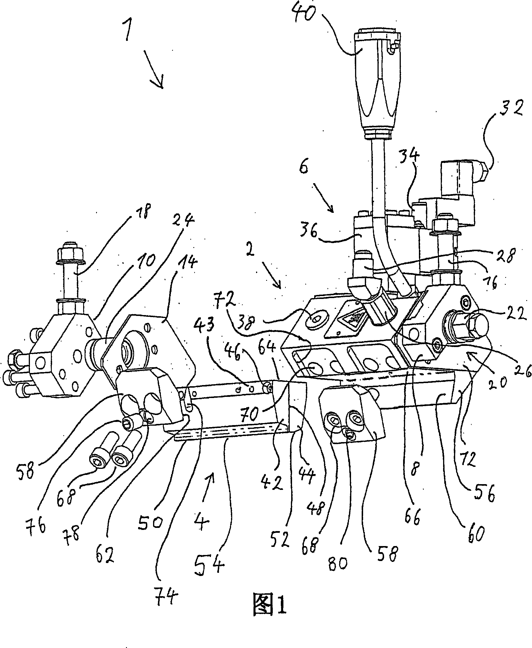
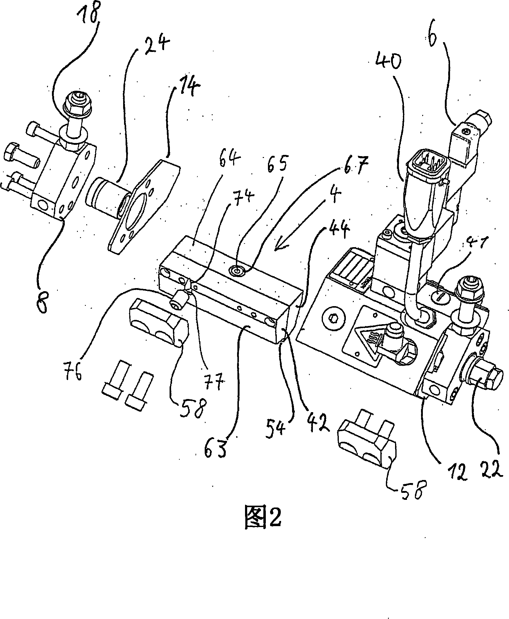
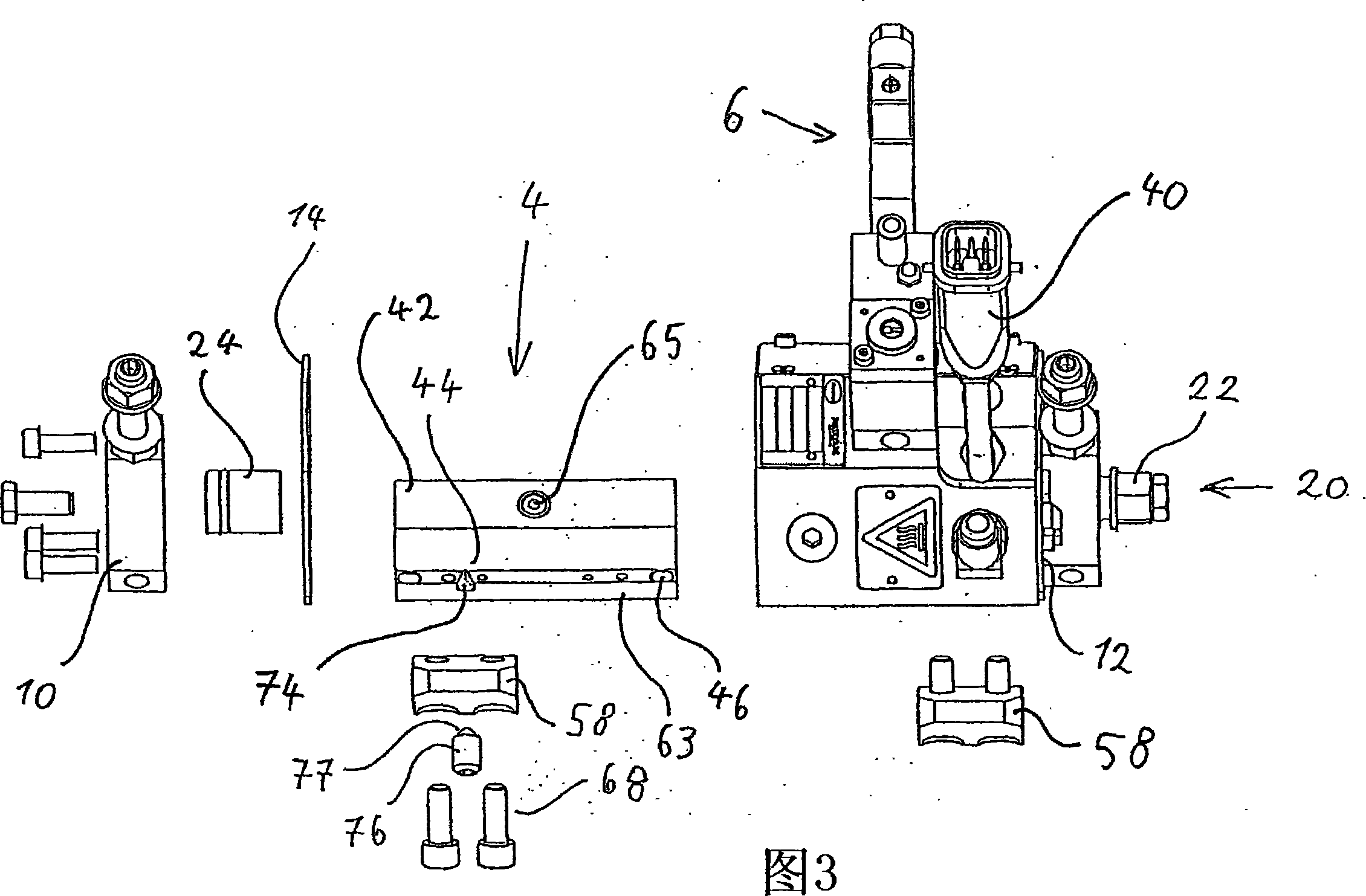
Coating device for coating liquid material

A coating device and coating technology, which are applied to the device, spray device, coating and other directions of coating liquid on the surface, can solve the problems of different material strengths of hot melt adhesives, avoid wasting bolts, improve compatibility, realize Effect of Nozzle Device Structure

Active Publication Date: 2008-05-28
NORDSON CORP
View PDF0 Cites 9 Cited by
  • Summary
  • Abstract
  • Description
  • Claims
  • Application Information

AI Technical Summary

Problems solved by technology

[0007] In addition, the known application devices have the disadvantage that, depending on where the hotmelt is applied along the nozzle slot, undesirably different material strengths of the hotmelt can result.

Method used


Image

  • Coating device for coating liquid material
  • Coating device for coating liquid material
  • Coating device for coating liquid material

Examples


no. 2 example 1

[0076] Like the second exemplary embodiment, in the third exemplary embodiment, the coating device 301 also has five fastening elements 358 , however, they are at different distances from one another. Two main electrical connections 340 are provided in the coating device 301 .

[0077] According to a fourth exemplary embodiment shown in FIG. 22 , the base body 402 has a support surface 466 and a fixed clamping section 456 with a clamping section surface 460 . The support surface 466 and the clamping section surface 460 are arranged approximately perpendicular to each other. The nozzle arrangement 404 is fixed on the base body 402 via a retaining element 490 designed as a flat rail and a resilient clip 458 designed as a spring leaf. The locking element 490 and the spring leaf 458 each engage in a groove 492 or 494 of the nozzle arrangement 4 . In this, a slot 492 into which the stop element 490 engages is provided in the mouth adapter 442 . A slot 494 into which the spring t...


PUM


Abstract

The invention refers to an Applicator apparatus for the surface application of liquid material, in particular hot melt adhesive, comprising a main body, and a nozzle arrangeme having at least one slot applicator nozzle for the delivery of the liquid material. According to the invention a clamping device for fixing the nozzle arrangement to the main body is comprised.

Description

technical field [0001] The invention relates to a coating device for the flat coating of liquid materials according to the preamble of claim 1 . Background technique [0002] Various application devices, which are also described as application heads, are known for the planar application of liquid materials, in particular hot melt adhesives. The applicator has a substrate, a nozzle assembly for delivering liquid material, and a valve assembly for controlling the output of the material. In this respect, the nozzle arrangement as well as the valve arrangement are accommodated in the base body. Pressure is applied to the base body, so that the hot melt is introduced and passed on from there to the nozzle assembly. The further guidance from the base body to the nozzle arrangement is controlled by means of the valve arrangement, so that the delivery of the hot melt adhesive in the nozzle arrangement for coating the surface to be coated is controlled. [0003] For this purpose, ...

Claims


Application Information

Patent Timeline
Patent Type & Authority Applications(China)
IPC IPC(8): B05C9/00B05C11/00B05B13/02B05B15/06
CPCB05B15/065B05C5/001B05C5/0279B05C5/0258B05C5/0237B05B15/65
Inventor 贝恩沃德·施塔克
Owner NORDSON CORP
Why Eureka
Try Eureka