Sander
A grinding machine and driving mechanism technology, which is applied in the direction of grinding machines, grinding machine parts, portable motorized devices, etc., can solve the problems that the usability cannot fully satisfy the operator, achieve easy fixed position adjustment operations, improve operation efficiency, and realize The effect of using performance
- Summary
- Abstract
- Description
- Claims
- Application Information
AI Technical Summary
Problems solved by technology
Method used
Image

Examples
no. 1 Embodiment approach
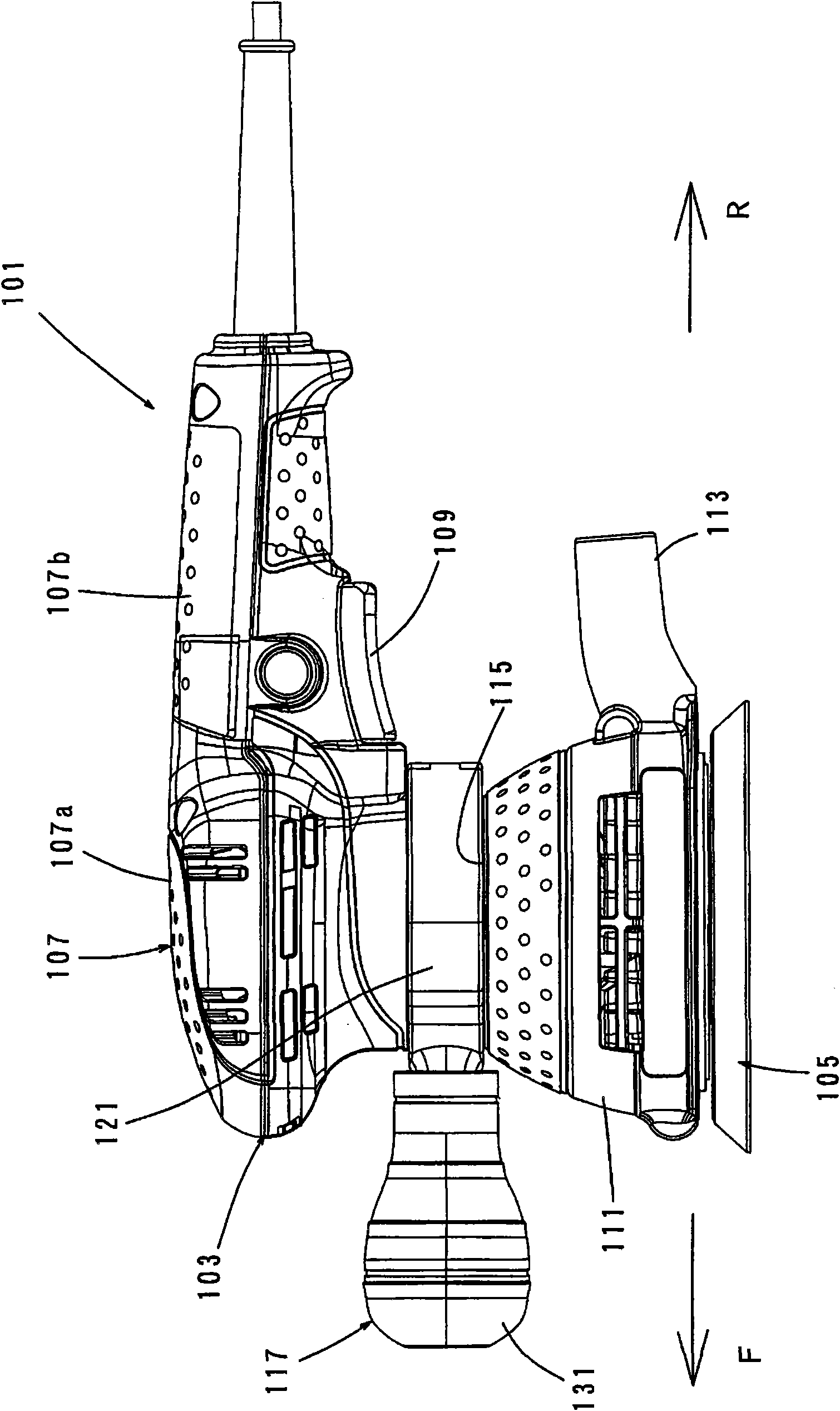
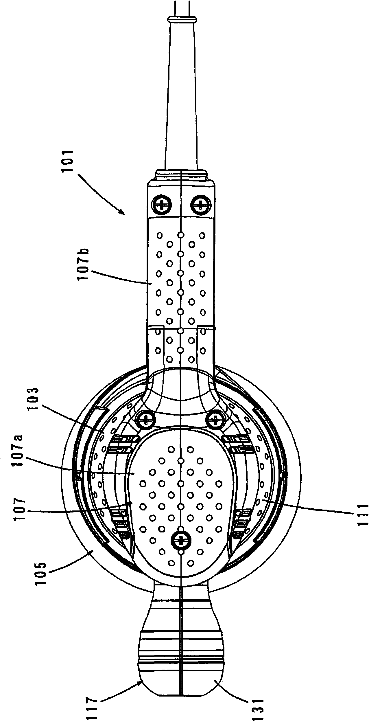
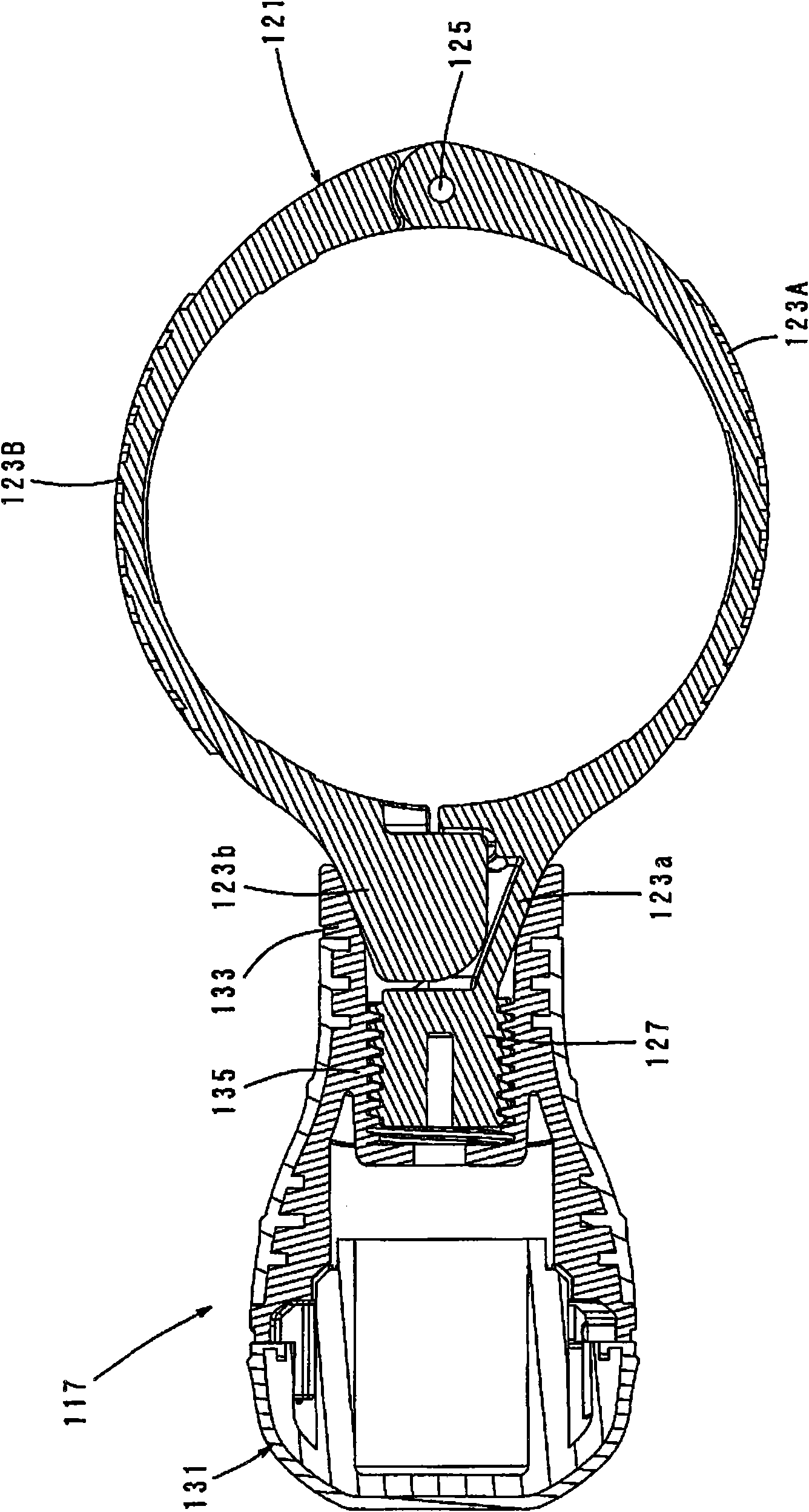
[0113] Below, refer to Figure 1 ~ Figure 3 The first embodiment of the present invention will be described in detail. Such as figure 1 As shown, the grinding machine 101 of the present embodiment mainly includes an electric motor (for convenience, its illustration is omitted) and a generally cylindrical motor housing for accommodating the electric motor and the power transmission mechanism (for convenience, its illustration is omitted). 103, and a grinding part 105, the grinding part 105 is provided in the axial direction of the motor housing 103 in a state extending downward from the motor housing 103 ( figure 1 the lower end side of the upper and lower directions). The motor housing 103 constitutes the main body of the tool, and corresponds to the "cylindrical housing" of the present invention. The power transmission mechanism decelerates and transmits the rotational power of the motor to the grinding unit 105, and corresponds to the "drive mechanism" of the present inve...
no. 2 Embodiment approach
[0131] Next, refer to Figure 4 and Figure 5 The structure of the auxiliary handle according to the second embodiment of the present invention will be described. Since there is no particular change in the overall structure of the sander 101 equipped with the auxiliary handle compared with the first embodiment, the same symbols are used and detailed descriptions thereof are omitted. In addition, such processing is not limited to the second embodiment, and is also the same in the third and subsequent embodiments.
[0132] The auxiliary handle 141 of the present embodiment mainly includes a ring-shaped handle connection part 143 and a grip part 147 for the operator to grasp in structure. The handle connection part 143 surrounds the handle formed on the motor housing 103 of the grinder 101 on the mounting part 115. The auxiliary handle 141 corresponds to the "movable handle" of the present invention, the handle connection part 143 corresponds to the "handle part" of the presen...
no. 3 Embodiment approach
[0141] Refer below Figure 6 and Figure 7 A third embodiment of the present invention will be described. This embodiment is a modified example of the auxiliary handle 141 of the second embodiment described above. That is, in this embodiment, the only difference from the second embodiment is that, on the auxiliary handle 141, nuts 151 are provided on the bases 145a, 145b of the handle connection part 143, and bolts 153 are provided on the grips. The other configurations of the grip 147 are the same as those of the second embodiment. As shown in the figure, the stepped through hole 147a with the hexagonal hole runs through the center of the grip portion 147, and the bolt 153 passes through the stepped through hole 147a with the hexagonal hole in a non-rotatable manner and is screwed on Nut 151. However, a form in which the bolt 153 is embedded in the grip portion 147 may also be employed.
[0142] According to the third embodiment having the above-mentioned structure, the ...
PUM
 Abstract
Description
Claims
Application Information