Synchronized Fastening Device
A fastening device and fastener technology, which is applied in the direction of transmission, gear transmission, transmission parts, etc., can solve the problems of high environmental index requirements, complex structure and complicated motion relationship, etc., and achieve simple transmission of motion relationship. , High fastening efficiency, and the effect of improving work efficiency
- Summary
- Abstract
- Description
- Claims
- Application Information
AI Technical Summary
Problems solved by technology
Method used
Image
Examples
Embodiment 1
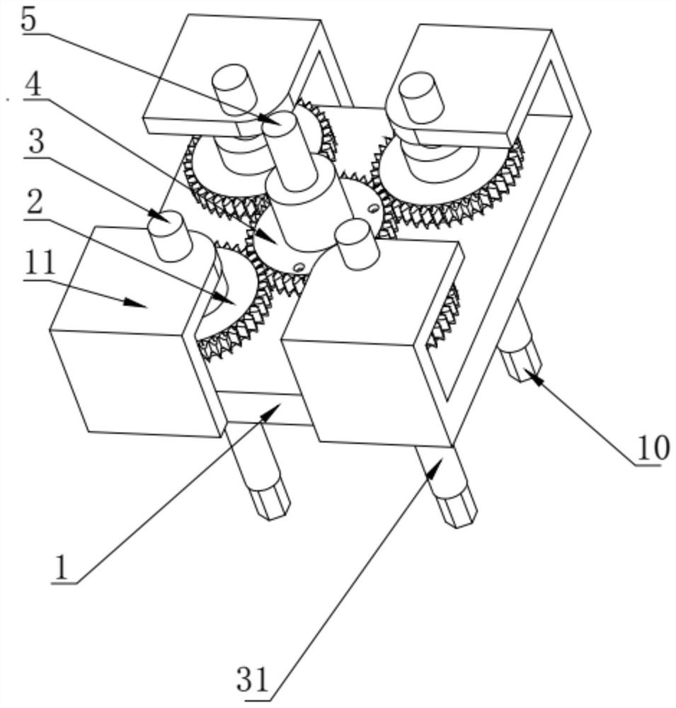
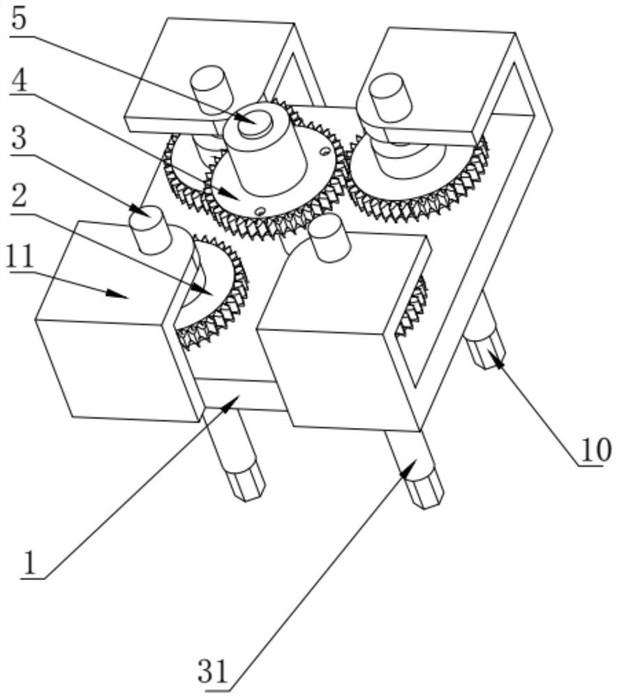
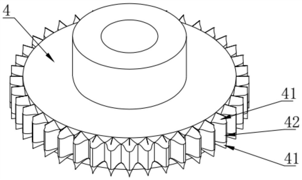
[0040] The axes of the driving gear 4 and the driven gear 2 are parallel to each other and staggered in the axial direction. When the driving gear 4 moves toward the driven gear 2, one of the cases is that the gap between the teeth of the driving gear 4 is just in line with the driven gear 2. The gear teeth of the driving gear 4 and the driven gear 2 can enter normal meshing without any rotation; in another case, when the centerlines of the teeth of the driving gear 4 and the driven gear 2 coincide in a mathematical sense, The driving gear 4 and the driven gear 2 cannot enter meshing; there is also a situation where the relative position of the driving gear 4 and the driven gear 2 is between the above two situations, that is, the gap between the teeth of the driving gear 4 and the driven gear 2. The teeth of the driving gear 2 are staggered from each other and the centerlines of the teeth of the two gears do not overlap, and the driving gear 4 and the driven gear 2 cannot enter...
Embodiment 2
[0058] The difference in structure between this embodiment and embodiment 1 is: as Figure 6 As shown, in order to reduce the input torque when the output torque is the same, so as to achieve labor-saving effect, reduce the input of power, and change the rotation direction of the output torque to make it the same as the rotation direction of the input torque, the present invention Several transition gears 8 are also provided. Specifically, a gear shaft 83 is fixedly installed on the base 1 , the transition gear 8 is sleeved on the gear shaft 83 and can rotate relative to the gear shaft 83 , and the transition gear 8 is externally meshed with the driving gear 4 and the driven gear 2 respectively. When the driving gear 4 and the transition gear 8 change from the disengaged state to the meshing state, the free rotation angle of the driven gear 2 can be reduced, so that the error of the rotation distance of the fastened part is smaller and the force on the fastened part is more un...
Embodiment 3
[0063] Preferably, as Figure 4 and Figure 5As shown, the applied torque is too large to cause deformation of the fastened part. The present invention also includes a protective structure for the fastened part. In order to better protect the fastened part, the protective structure includes a sleeve On the torque disc 6 on the fixed shaft 5 and the second elastic plunger 7 arranged on the outer peripheral surface of the torque disc 6, the driving gear 4 is provided with a pit 12 corresponding to the second elastic plunger 7, when When the torque applied on the torque disc 6 is less than or equal to the standard torque of the fastener, the second elastic plunger 7 can be embedded in the recess 12 to realize the synchronous rotation of the driving gear 4 with the torque disc 6, When the torque applied on the torque disc 6 is greater than the standard torque required by the fastener, the second elastic plunger 7 can break away from the pit 12, and the driving gear 4 no longer ro...
PUM
 Abstract
Description
Claims
Application Information
 - R&D
- Intellectual Property
- Life Sciences
- Materials
- Tech Scout
- Unparalleled Data Quality
- Higher Quality Content
- 60% Fewer Hallucinations
Browse by: Latest US Patents, China's latest patents, Technical Efficacy Thesaurus, Application Domain, Technology Topic, Popular Technical Reports.
© 2025 PatSnap. All rights reserved.Legal|Privacy policy|Modern Slavery Act Transparency Statement|Sitemap|About US| Contact US: help@patsnap.com


