
Heavy oil thermal recovery flow field change simulation experimental device

A heavy oil thermal recovery and experimental device technology, which is applied in the fields of production fluids, earthwork drilling, wellbore/well components, etc. Oil dynamic changes and development methods, etc., to achieve the effect of wide distribution of measuring points

Active Publication Date: 2020-05-26
CHINA PETROLEUM & CHEM CORP +1
View PDF14 Cites 1 Cited by
  • Summary
  • Abstract
  • Description
  • Claims
  • Application Information

AI Technical Summary

Problems solved by technology

[0002] The physical simulation experimental devices currently used in the thermal recovery process are mainly divided into one-dimensional and three-dimensional devices. The one-dimensional and three-dimensional experimental devices are mainly used to simulate the reservoir temperature under different parameters such as permeability, oil saturation, crude oil viscosity, and reservoir heterogeneity. field and pressure field, as well as the reservoir temperature and pressure field under different injection-production techniques, it is impossible to evaluate the change law of saturation field under multi-factor conditions, and it is impossible to describe the impact of multi-flow field changes in the process of thermal recovery. The influence of the displacement effect, and the inability to deeply explore the dynamic changes of crude oil distribution and the oil displacement mechanism of the development mode of heavy oil under different thermal recovery methods have affected the application prospects of new technologies in the field

Method used


Image

  • Heavy oil thermal recovery flow field change simulation experimental device
  • Heavy oil thermal recovery flow field change simulation experimental device
  • Heavy oil thermal recovery flow field change simulation experimental device

Examples


Embodiment Construction

[0026] In order to make the above and other objects, features and advantages of the present invention more comprehensible, the preferred embodiments are listed below and shown in the accompanying drawings in detail as follows.

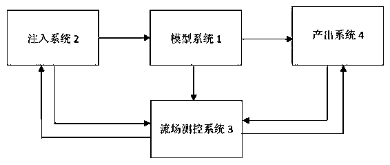
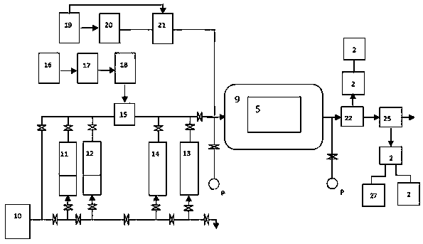
[0027] Such as figure 1 as shown, figure 1 It is a block diagram of the experimental device for flow field change in heavy oil thermal recovery of the present invention. The experimental device for simulating flow field change in heavy oil thermal recovery includes four parts: injection system 2 , model system 1 , flow field measurement and control system 3 and output system 4 .

[0028] The injection system 2 is connected to the model system 1, and injects high-viscosity oil, chemical agent, gas and steam into the model system 1.

[0029] The flow field measurement and control system 3 is connected to the model system 1, the injection system 2 and the output system 4, collects the parameters of the model system 1, the injection system 2 and the outpu...


PUM


Abstract

The invention provides a heavy oil thermal recovery flow field change simulation experimental device which comprises an injection system, a model system, a flow field measurement and control system and an output system. The model system simulates heavy oil thermal recovery flow field changes. The injection system is connected to the model system and injects high-viscosity oil, water, chemical agents, gas and water vapor into the model system. The flow field measurement and control system is connected to the model system, the injection system and the output system, acquires data of working parameters of the model system, the injection system and the output system, transmits data control signals to the model system, the injection system and the output system and processes the data of the acquired parameters. The output system is connected to the model system, collects the oil, the gas and water output by the model system and then separates and measures the oil, the gas and the water. Theheavy oil thermal recovery flow field change simulation experimental device can evaluate the change rule of a saturation field under various factor conditions and carry out researches on dynamic changes of crude oil distribution in different thermal recovery modes.

Description

technical field [0001] The invention relates to the technical field of indoor experimental devices for thermal recovery of petroleum, in particular to an experimental device for simulating flow field changes in thermal recovery of heavy oil. Background technique [0002] The physical simulation experimental devices currently used in the thermal recovery process are mainly divided into one-dimensional and three-dimensional devices. The one-dimensional and three-dimensional experimental devices are mainly used to simulate the reservoir temperature under different parameters such as permeability, oil saturation, crude oil viscosity, and reservoir heterogeneity. field and pressure field, as well as the reservoir temperature and pressure field under different injection-production techniques, it is impossible to evaluate the change law of saturation field under multi-factor conditions, and it is impossible to describe the impact of multi-flow field changes in the process of thermal...

Claims


Application Information

Patent Timeline
IPC IPC(8): E21B43/24E21B49/00
CPCE21B43/24E21B49/00
Inventor 蔡文斌谢志勤白艳丽王善堂何绍群李淑兰张仲平李友平刘冬青殷方好
Owner CHINA PETROLEUM & CHEM CORP
Learn More