Mine safety production monitoring method

A technology for safe production and mines, applied in the direction of comprehensive factory control, comprehensive factory control, program control, etc., can solve the problem of difficult to find mutually compatible systems, and achieve a large number of measuring points, strong anti-interference, and simple interface. Effect

Inactive Publication Date: 2018-07-06
HARBIN DONGZHUAN TECH
View PDF0 Cites 0 Cited by
  • Summary
  • Abstract
  • Description
  • Claims
  • Application Information

AI Technical Summary

Problems solved by technology

However, since the existing monitoring systems almost all use their own dedicated communication protocols, it is difficult to find two mutually compatible systems

Method used


Image

  • Mine safety production monitoring method

Examples


Embodiment 1

[0014] Mine safety production monitoring method, using CAN bus to form a peer-to-peer inter-layer field bus network. Using priority arbitration technology, when bus access conflicts occur, high-priority information can still be sent, which is more suitable for data processing in mines. For systems with high requirements for transmission and real-time control, the CAN bus communication protocol and interface are simple, the transmission rate is high, it has a variety of error detection methods, and it has strong anti-interference. It encodes communication data blocks and easily realizes point-to-point communication. The length of the data segment is up to 8 bytes, which can meet the general requirements of control commands, working status and test data. For traditional mine reconstruction, only the RS-485 nodes need to be replaced by CAN nodes, and the information in the original system The transmission interface, monitoring system software and workstation are respectively repla...

Embodiment 2

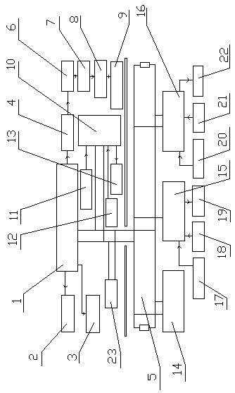
[0016] A mine safety production monitoring method, the monitoring system host is respectively connected to the dispatching panel 2, the camera 3, the video converter 4 and the CAN bus 5, the video converter is connected to the modulator 6, and the modulator is connected to the matching The device 7 is connected, the matching device is connected to the TV network server 8, the TV network server is connected to the industrial TV system 9, the CANL output terminal and the CANH output terminal of the CAN bus are connected to the CAN workstation interface 10 on the well, The CAN workstation interface on the well is respectively connected with the sensor 11 on the well, the power supply box 12 on the well and the power breaker 13 on the well, and the CAN bus is respectively connected to the CAN workstation interface one 14, the CAN workstation interface two 15 and the CAN workstation interface in the well Three 16 connections.

[0017] Example 2:

[0018] According to the mine safe...

Embodiment 3

[0020] According to the mine safety production monitoring method described in embodiment 1 or 2, the CANH output terminal and the CANL output terminal of the CAN bus are connected to the lightning arrester 23 .


PUM


Abstract

The invention provides a mine safety production monitoring method. Almost all existing monitoring systems use their own dedicated communication protocols, so that it is difficult to find two compatible systems. According to the mine safety production monitoring method provided by the invention, a peer-to-peer inter-layer field bus network is formed by adopting a CAN bus, the priority arbitration technology is adopted, the information with high priority can still be transmitted in the case of a bus access conflict, the length of a data segment of the CAN bus is 8 bytes at most, the general requirements of control commands, working states and test data can be met, for the traditional mine reconstruction, an RS-485 node is just replaced with a CAN node, an information transmission interface,monitoring system software and a workstation in the original system are replaced with a CAN interface adapter, monitoring system software applicable to a CAN communication protocol and a CAN-based workstation separately, a monitoring host can also be connected with a server to access a local area network and the Internet so as to implement remote browsing and control. The mine safety production monitoring method provided by the invention is applied to mine safety production monitoring.

Description

Technical field: [0001] The invention relates to a mine safety production monitoring method. Background technique: [0002] my country's mine safety production monitoring system has experienced a comprehensive monitoring process from scratch, from simple to complex, from integrated machine to network, from secondary network to multi-level network. After more than ten years of application, the mine safety production monitoring system has played a significant role in my country's coal mine safety production and modern management. However, since the existing monitoring systems almost all use their own dedicated communication protocols, it is difficult to find two mutually compatible systems. At present, the compatibility of the information transmission system has become a restrictive factor for the bureaus and mines equipped with the monitoring system to further expand the system functions. Therefore, finding a way to solve the system compatibility problem is of great signifi...

Claims


Application Information

Patent Timeline
Patent Type & Authority Applications(China)
IPC IPC(8): H04L12/40H04N7/18E21F17/18G05B19/418
CPCY02P90/02H04L12/40026E21F17/18G05B19/4185H04L2012/40215H04N7/18
Inventor 王冠红
Owner HARBIN DONGZHUAN TECH
Why Eureka
Try Eureka