Winding device for coil with air passage and winding method of winding device

A winding device and coil technology, applied in the direction of transformer/inductor coil/winding/connection, electrical components, parts of transformer/inductor, etc., can solve the problem of no proposed coil, easy rebound and loose, no open winding equipment, etc. Problems, to achieve the effect of convenient mobile adjustment, convenient and reliable use

Pending Publication Date: 2020-05-29
福州富和电子科技有限公司
View PDF2 Cites 0 Cited by
  • Summary
  • Abstract
  • Description
  • Claims
  • Application Information

AI Technical Summary

Problems solved by technology

The inner coils of two adjacent pie-shaped coils are separated by a second spacer, and the outer coils of two adjacent pie-shaped coils are separated by a third spacer to form a second airway. The airway and the third airway are obtained by separating the inner coil and the outer coil through the first partition block and the fourth partition block; this application mainly realizes the coil winding of the first airway and the third airway similar to the patent, but The winding method of this patent only discloses that spacers need to be set in the inner and outer coils, and does not disclose how to use any winding equipment to carry out the winding method, nor does it disclose how the spacers are adjusted and set; and it also does not disclose There is no technical problem and technical solution to the problem that the coil is easy to rebound and loose after winding

Method used


Image

  • Winding device for coil with air passage and winding method of winding device
  • Winding device for coil with air passage and winding method of winding device
  • Winding device for coil with air passage and winding method of winding device

Examples


Embodiment Construction

[0042] Below in conjunction with accompanying drawing and specific embodiment the present invention is described in further detail:

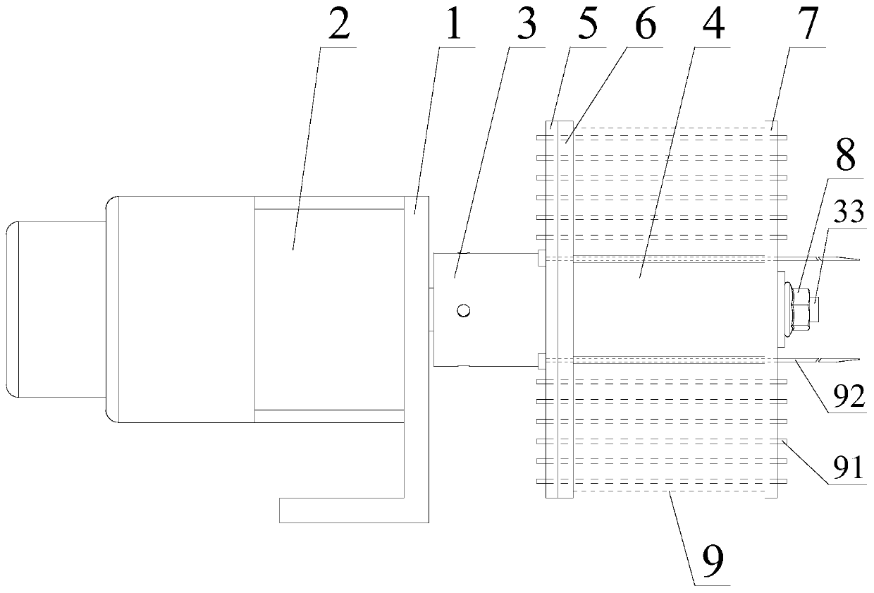
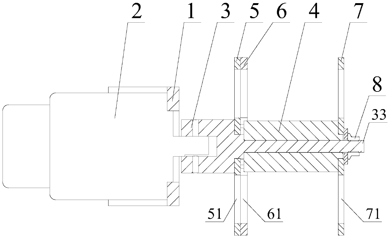
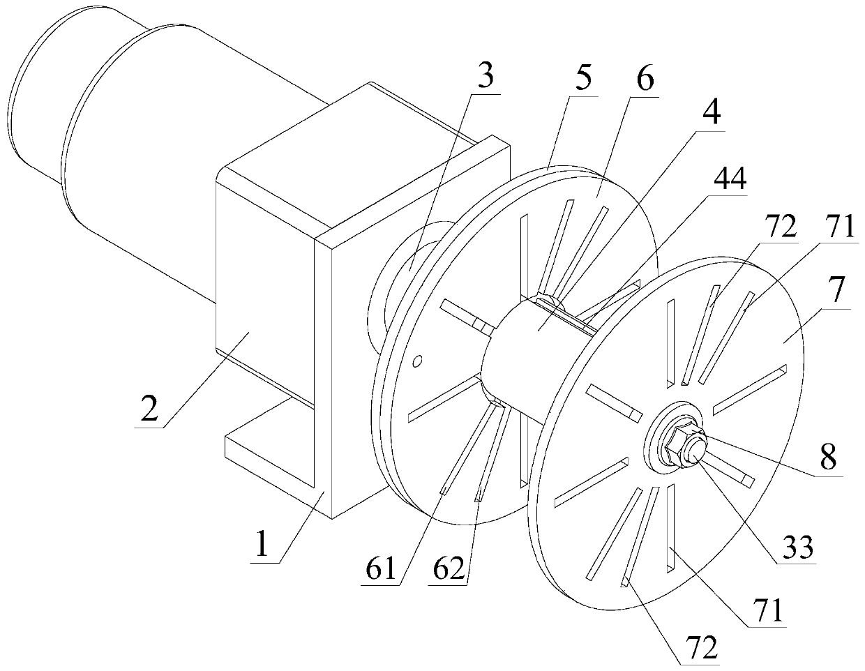
[0043] see Figure 1-9 As shown, a winding device with an airway coil includes a motor mounting frame 1 and a winding motor 2 mounted on it, the output shaft of the winding motor 2 is provided with a winding connection shaft 3, the One end of the winding connection shaft 3 is provided with a winding positioning step 31, the winding positioning step 31 is connected with a winding shaft 32, the end of the winding shaft 32 is provided with a screw rod 33, and on the winding positioning step 31 A positioning sleeve 4 is connected, and a left end splint 5 and an inner splint 6 are provided between the positioning sleeve 4 and the winding positioning step 31, and the other end of the positioning sleeve 4 is provided with a right end splint 7. The positioning bushing 4, the left end splint 5, the inner splint 6 and the right end splint 7 are locked an...


PUM


Abstract

The invention discloses a winding device for a coil with an air passage and a winding method of the winding device. The winding device comprises a motor mounting frame and a winding motor mounted on the motor mounting frame, and a winding connecting shaft is arranged on an output shaft of the winding motor; a winding positioning step is arranged at one end of the winding connecting shaft; a winding shaft is connected to the winding positioning step; a screw rod is arranged at an end head of the winding shaft; the winding positioning step is connected with a positioning shaft sleeve; and a leftend clamping plate and an inner clamping plate are arranged between the positioning shaft sleeve and the winding positioning step, a right end clamping plate is arranged at the other end of the positioning shaft sleeve, and the positioning shaft sleeve, the left end clamping plate, the inner clamping plate and the right end clamping plate are locked and fixed to the winding connecting shaft through locking nuts and the screw rod and rotate along with the winding motor. According to the winding device, winding of high-power multi-layer coils with the air passages of different sizes and diameters can be conveniently achieved, the wound coils are stable in shape after being tightened, the wound coils cannot rebound or loosen when being taken down from the winding device, production cost canbe reduced, and production benefits are improved.

Description

technical field [0001] The invention relates to the technical field of wire winding in the electronics industry, in particular to a wire winding device for a coil with an air channel and a winding method thereof. Background technique [0002] There are usually coils in power transformers or inductance products, and the coils will generate heat when they work, especially for large coils with high voltages. If the heat generated cannot be discharged in time, the reliability of the coils will be affected and the service life will be affected. It will also be greatly reduced, so it is necessary to ensure that the coil has a good heat dissipation structure. The coil used in large and high-voltage occasions has a large current, and it relies on convective air cooling when used. There is no winding skeleton inside the coil. Axial air passages and amplitude Heat dissipation and cooling is carried out to the air passage, and with the increase of the coil capacity, the number of air p...

Claims


Application Information

Patent Timeline
IPC IPC(8): H01F41/098H01F27/28
CPCH01F27/2876H01F41/098
Inventor 张河海
Owner 福州富和电子科技有限公司
Why Eureka
Try Eureka