Motion mechanism with self-powered mechanism and communication network

A motion mechanism, self-powered technology, used in electrical components, circuit devices, transmission systems, etc.

Active Publication Date: 2020-05-29
HARBIN UNIV OF SCI & TECH +1
View PDF4 Cites 1 Cited by
  • Summary
  • Abstract
  • Description
  • Claims
  • Application Information

AI Technical Summary

Problems solved by technology

The direct detection method involves the installation of the detection device on the motion mechanism, and its power supply, reliability, and data transmission problems are all facing challenges

Method used


Image

  • Motion mechanism with self-powered mechanism and communication network
  • Motion mechanism with self-powered mechanism and communication network
  • Motion mechanism with self-powered mechanism and communication network

Examples


Embodiment approach

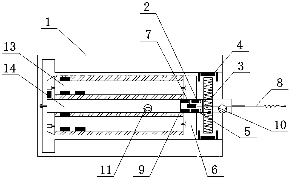
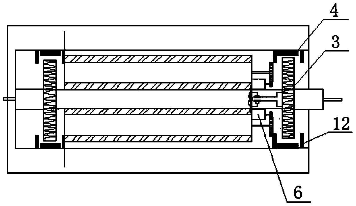
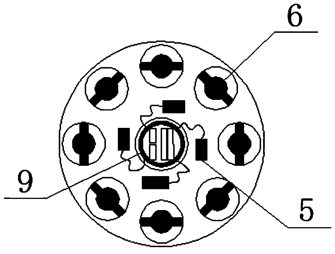
[0025] see Figure 1-5 Describe a preferred embodiment of the present invention, a motion mechanism with a self-power supply mechanism, which includes a first body 1, a second body 14, a self-power supply mechanism, a first power conversion mechanism 2 and an electric load: wherein, the first The two bodies 14 are arranged inside or outside the first body 1, and when the motion mechanism works, the two bodies move relative to each other. In this embodiment, the second body 14 is located inside the first body 1, and the two are arranged axially. When the movement mechanism is working, the second body 14 rotates around its own axis, and the self-power supply mechanism is connected with the first power conversion mechanism 2. The number of electric loads is one or more, the first power conversion mechanism 2 is connected to one or more electric loads respectively, the self-power supply mechanism includes a generating winding 3 and a magnetic field generating mechanism 4, and the ...


PUM


Abstract

The invention provides a motion mechanism with a self-powered mechanism and a communication network, belongs to the field of motion mechanisms, and particularly relates to the motion mechanism with the self-powered mechanism and the communication network. The problems of complex power supply form and poor reliability of an electric load on an existing motion mechanism are solved. The motion mechanism comprises a first body, a second body, a self-powered mechanism, a first power conversion mechanism and an electric load, the second body is arranged inside or outside the first body, the self-powered mechanism is connected with the first power conversion mechanism, the first power conversion mechanism is connected with the electric load, the self-powered mechanism comprises a power generationwinding and a magnetic field generation mechanism, the power generation winding is arranged on the second body, the magnetic field generation mechanism is arranged on the first body, and the magneticfield generation mechanism is arranged on the outer side or the inner side of the power generation winding and moves relative to a magnetic field generated by the magnetic field generation mechanism.The self-powered mechanism is mainly used for self-powering the electric load on the motion mechanism.

Description

technical field [0001] The invention belongs to the field of motion mechanisms, in particular to a motion mechanism with a self-power supply mechanism and a communication network. Background technique [0002] Existing kinematic mechanisms often use non-contact detection and indirect measurement methods for the state and parameters of the kinematic mechanism itself because its working state is in motion. With various defects. The direct detection method involves the installation of the detection device on the motion mechanism, and its power supply, reliability, and data transmission problems are all faced with challenges. Contents of the invention [0003] In order to solve the problems in the prior art, the present invention proposes a motion mechanism and a communication network with a self-power supply mechanism. [0004] In order to achieve the above object, the present invention adopts the following technical solutions: a motion mechanism with a self-power supply me...

Claims


Application Information

Patent Timeline
Patent Type & Authority Applications(China)
IPC IPC(8): H04B5/00H02J50/10H02J5/00
CPCH04B5/0037H02J50/10
Inventor 张辉戈宝军张妨陶大军赵丽娜于鑫韩斌吴凤桐孙明
Owner HARBIN UNIV OF SCI & TECH
Why Eureka
Try Eureka