Display panel, driving method thereof and display device

A technology of display panel and driving cycle, applied in static indicators, instruments, etc., can solve problems such as affecting normal display, increasing power consumption of liquid crystal displays, and adversely saving power consumption, and achieves narrow frame design, reduction in number, and reduction in power consumption. The effect of occupied space

Pending Publication Date: 2020-06-02
XIAMEN TIANMA MICRO ELECTRONICS
View PDF8 Cites 1 Cited by
  • Summary
  • Abstract
  • Description
  • Claims
  • Application Information

AI Technical Summary

Problems solved by technology

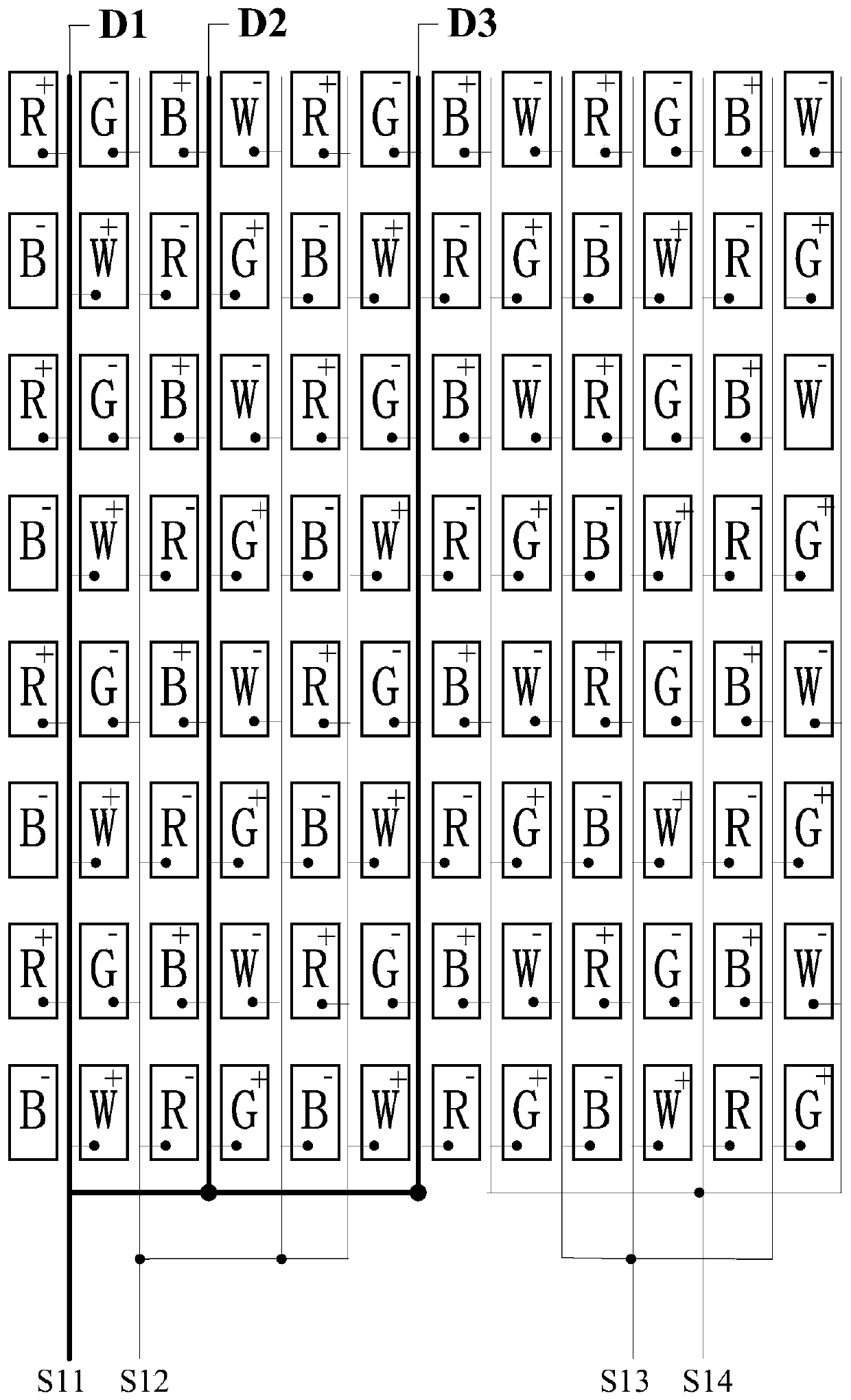
Usually, in the same time frame, the polarities of the data signals received by two adjacent sub-pixels along the row direction are opposite. The data line corresponding to the same data signal terminal is not only connected to the red sub-pixel, but also connected to the blue and green sub-pixels. Therefore, the data that the data signal terminal needs to provide to the red sub-pixel is 255. When scanning the blue sub-pixel or When the green sub-pixel is used, the data that the data signal terminal needs to provide to the blue sub-pixel or the green sub-pixel is 0. Therefore, when scanning the same pixel row, the data signal sent by the same data signal terminal needs to flip / jump multiple times , which will greatly increase the power consumption of the liquid crystal display, which is not conducive to saving power consumption
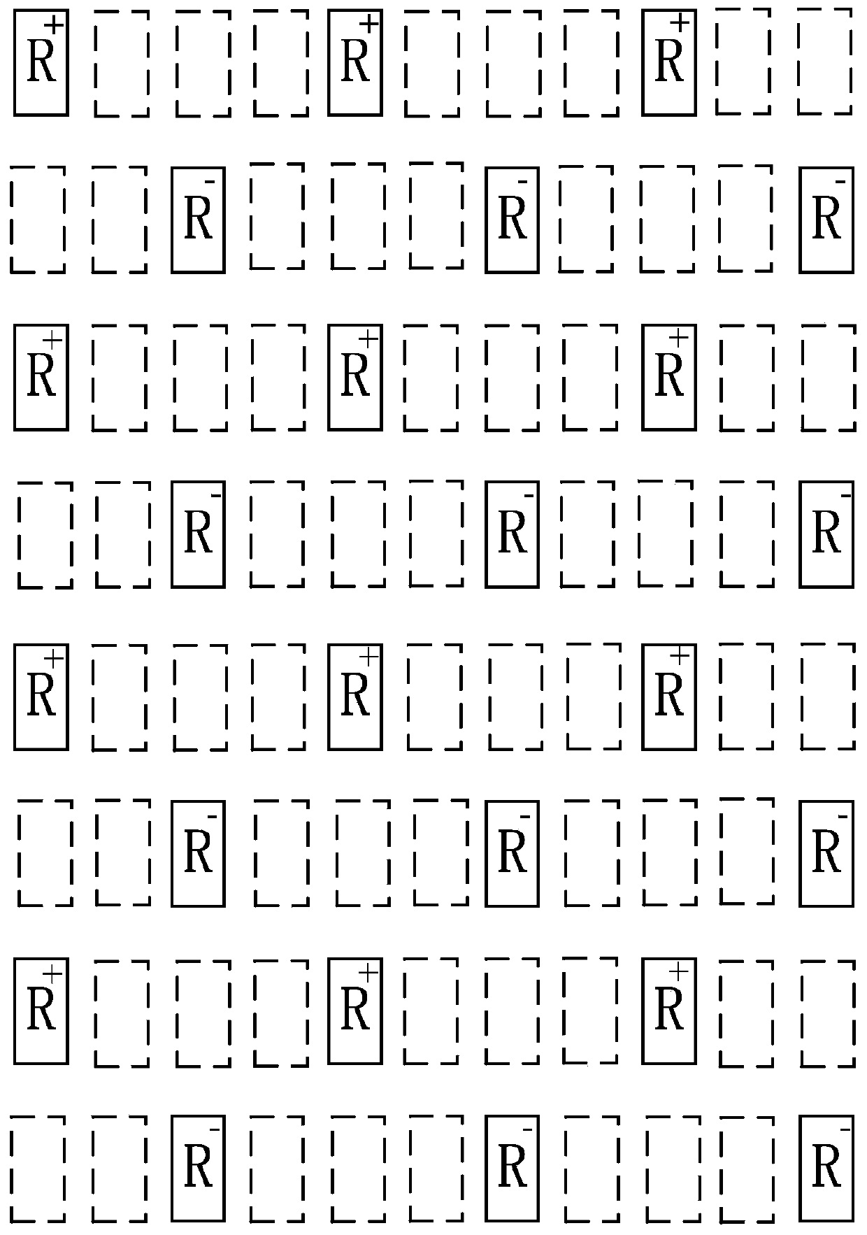
Moreover, in a solid-color display screen, taking a red screen as an example, the polarities of the data signals received by the red sub-pixels in the same pixel row are the same, and the polarities of the data signals received by the red sub-pixels in the odd-numbered and even-numbered rows are opposite, so , when scanning progressively, there will be a positive line and a negative line, which will cause crosstalk (crosstalk) problems on the display panel and affect the normal display

Method used


Image

  • Display panel, driving method thereof and display device
  • Display panel, driving method thereof and display device
  • Display panel, driving method thereof and display device

Examples


Embodiment Construction

[0036]Various exemplary embodiments of the present invention will now be described in detail with reference to the accompanying drawings. It should be noted that the relative arrangements of components and steps, numerical expressions and numerical values ​​set forth in these embodiments do not limit the scope of the present invention unless specifically stated otherwise.

[0037] The following description of at least one exemplary embodiment is merely illustrative in nature and in no way taken as limiting the invention, its application or uses.

[0038] Techniques, methods and devices known to those of ordinary skill in the relevant art may not be discussed in detail, but where appropriate, such techniques, methods and devices should be considered part of the description.

[0039] In all examples shown and discussed herein, any specific values ​​should be construed as exemplary only, and not as limitations. Therefore, other instances of the exemplary embodiment may have diff...


PUM


Abstract

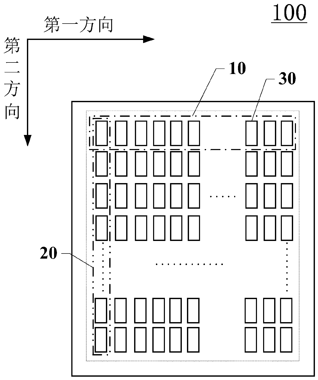
The invention discloses a display panel, a driving method thereof and a display device and relates to the technical field of display. In the same pixel row, the colors of sub-pixels electrically connected with data lines corresponding to the same data signal end are the same; in the same time frame, the polarities of data signals sent by the same data signal end to the sub-pixels electrically connected with the corresponding data lines are the same; the same time frame comprises a first driving period and a second driving period; in the first driving period, odd pixel rows are scanned in sequence; in the second driving period, even pixel rows are scanned in sequence; the first driving period is adjacent to the second driving period; and in the first driving period, polarities of data signals received by any adjacent odd sub-pixels in the first direction are the same; and in the second driving period, the polarities of the data signals received by any adjacent even-numbered rows of sub-pixels in the first direction are the same. Therefore, the panel power consumption is saved, and the crosstalk problem is solved.

Description

technical field [0001] The present invention relates to the field of display technology, and more specifically, to a display panel, a driving method thereof, and a display device. Background technique [0002] Liquid crystal display is a flat and ultra-thin display device, which consists of a certain number of color or black and white pixels, placed in front of the light source or reflective surface. Liquid crystal displays consume very little power, making them favored by engineers for electronic devices that run on batteries. Its main principle is to stimulate liquid crystal molecules with current to generate points, lines, and surfaces to form a picture with the back lamp tube. [0003] Generally, a liquid crystal display is provided with several sub-pixels, the sub-pixels form sub-pixel rows and sub-pixel columns, each sub-pixel row includes a plurality of pixel units, and each pixel unit usually includes red sub-pixels, green sub-pixels and blue sub-pixels. In the dis...

Claims


Application Information

Patent Timeline
Patent Type & Authority Applications(China)
IPC IPC(8): G09G3/36
CPCG09G3/3607G09G3/3677G09G2330/021
Inventor 孟垂玉周洪波伍黄尧周秀峰
Owner XIAMEN TIANMA MICRO ELECTRONICS
Why Eureka
Try Eureka