
Plate grate sieve plate for vibrating sieve and vibrating sieve

A vibrating screen and grate technology, which is applied in the direction of filter screen, solid separation, grille, etc., can solve the problems of short service life, low screening precision, and difficulty in cleaning materials, so as to achieve long service life, reduce cleaning difficulty, and improve The effect of screening efficiency

Active Publication Date: 2020-06-05
辽宁维特机械设备制造有限公司
View PDF10 Cites 0 Cited by
  • Summary
  • Abstract
  • Description
  • Claims
  • Application Information

AI Technical Summary

Problems solved by technology

[0004] In order to solve the above technical problems, the present invention provides a grate sieve plate for a vibrating screen and a vibrating screen, which solves the problems of low screening accuracy, short service life and difficulty in cleaning materials in the existing vibrating screen

Method used


Image

  • Plate grate sieve plate for vibrating sieve and vibrating sieve
  • Plate grate sieve plate for vibrating sieve and vibrating sieve
  • Plate grate sieve plate for vibrating sieve and vibrating sieve

Examples


Embodiment 1

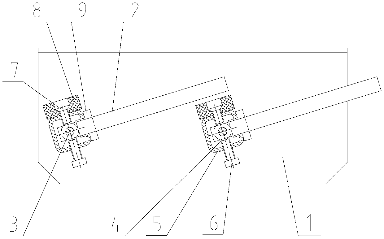
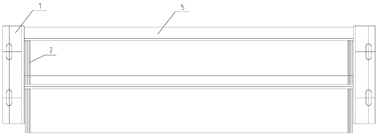
[0027] refer to figure 1 , figure 2 and image 3 , a grate sieve plate for a vibrating screen of the present invention, comprising two side plates 1 and a plurality of grate sieve units installed between the two side plates 1, the grate sieve unit comprising a grate bar series assembly and a plurality of The grate bar 2, the grate bar series assembly includes the shaft 3, the spacer 4, the C-shaped groove 5 and the bolt 6, one end of the grate bar 2 is drilled, and the grate bar 2 and the spacer 4 are connected by two grate bars. The strips 2 are connected in series on the shaft 3 in the form of separating the spacers 4, and then installed in the C-shaped groove 5 as a whole. A bolt 6 is set on the C-shaped groove 5 of the C-shaped groove 5, and the upper end of the bolt 6 is supported on the spacer 4. Both ends of the C-shaped groove 5 and the shaft 3 are fixed on the two side plates 1, and the opening of the C-shaped groove 5 faces upward. Tilt at a certain angle; the un...

Embodiment 2

[0036] Different from Example 1, refer to Figure 4 , the side plate 1 is fixedly connected by a plurality of side plate units, two grate sieve units are arranged between each two corresponding side plate units, and the entire grate sieve plate is arranged inclined downward. The advantage of this embodiment is that the length of the grate sieve plate can be flexibly set according to the length required by the vibrating screen.


PUM


Abstract

The invention relates to the technical field of sieve plates of vibrating sieves, and particularly provides a plate grate sieve plate for a vibrating sieve and the vibrating sieve. The plate grate sieve plate comprises two side plates and a plurality of plate grate sieve units which are mounted between the two side plates, wherein each plate grate sieve unit comprises a plate grate strip series-connection assembly and a plurality of plate grate strips, the plate grate strip series-connection assembly comprises a shaft, a fixed-distance sheet, a C-shaped slot and a bolt, ends of the plate gratestrips are drilled, the plate grate strips and the fixed-distance sheet are in series connection on the shaft in a mode of separating the two plate grate strips by the fixed-distance sheet, and are integrally mounted in the C-shaped slot, the opening width of the C-shaped slot is greater than that of the plate grate strips, a bolt is arranged on the C-shaped slot below the fixed-distance sheet, the upper end of the bolt abuts against the fixed-distance sheet, the two ends of the C-shaped slot and the two ends of the shaft are fixedly arranged on the two side plates, and the opening surface ofthe C-shaped slot upwards tilts by certain angle. The plate grate sieve plate solves the problems that existing vibrating sieve is low in sieving precision, is short in service life and is difficultin material clearing.

Description

technical field [0001] The invention relates to the technical field of vibrating sieve plates, and in particular provides a grate sieve plate for vibrating sieves and a vibrating sieve. Background technique [0002] The grates used in the grate vibrating screen in the prior art are all round rods, and the screening gap is actually the distance between two lines. During the screening process, it is easy to be worn by the material, causing the screen The separation gap becomes larger, the screening accuracy is low, and the service life is short; [0003] In addition, the grates used in the existing grate vibrating screen are fixed, and materials that are about the same size as the gaps between the grate bars are easily caught in the gaps, resulting in the need to continuously clean the grate on the sieve plate through a beating device. For materials, the noise generated by beating is very loud and the effect is not obvious, and the work efficiency is low. Contents of the in...

Claims


Application Information

Patent Timeline
IPC IPC(8): B07B1/46B07B1/28
CPCB07B1/28B07B1/46B07B1/4609
Inventor 付文军曲永富
Owner 辽宁维特机械设备制造有限公司
Learn More