Full-automatic pipe mouth shaping machine for U-shaped copper pipe

A fully automatic, shaping machine technology, applied in the field of copper tube production equipment, can solve problems such as low shaping efficiency, and achieve the effects of improving shaping efficiency, increasing production output, and reducing personnel costs

Pending Publication Date: 2020-06-05
绍兴市凯杰铜业有限公司
View PDF0 Cites 2 Cited by
  • Summary
  • Abstract
  • Description
  • Claims
  • Application Information

AI Technical Summary

Problems solved by technology

[0002] U-shaped copper tubes are common pipe connectors in existing refrigeration systems. U-shaped copper tubes are usually bent and formed by straight copper tubes. The pipe fittings are shaped so that the two nozzles on the U-shaped copper pipe are parallel, and the center distance between the nozzle

Method used


Image

  • Full-automatic pipe mouth shaping machine for U-shaped copper pipe
  • Full-automatic pipe mouth shaping machine for U-shaped copper pipe
  • Full-automatic pipe mouth shaping machine for U-shaped copper pipe

Examples


Embodiment

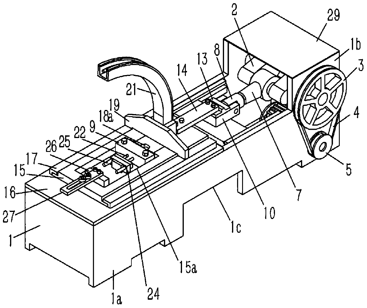
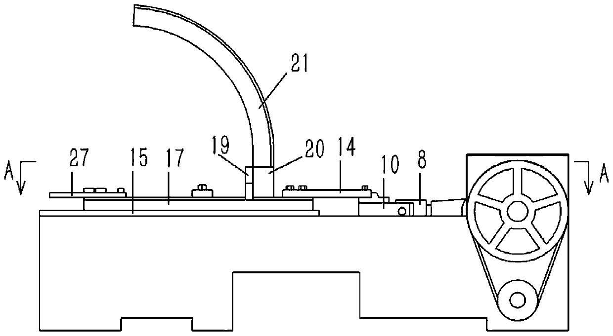
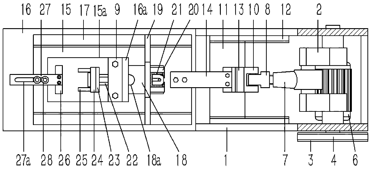
[0022] Example: see Figures 1 to 6 As shown, the U-shaped copper tube automatic nozzle shaping machine includes a frame 1. The frame 1 is composed of a rectangular frame. On the two side frames at the right end of the frame 1, an upwardly extending support plate 1b is formed. The support plate 1b There is a crankshaft 2 between them, and the two ends of the crankshaft 2 are hinged on the support plate 1b of the frame 1 through bearings, and one end of the crankshaft 2 passes through the support plate 1b to insert and fix the driven pulley 3, and the driven pulley 3 passes through the The transmission belt 4 is connected with the driving pulley 5, the driving pulley 5 is inserted and fixed on the rotating shaft of the motor 6, and the motor 6 is fixed on the frame 1;

[0023] The crankshaft 2 is hinged with a connecting rod 7, and the other end of the connecting rod 7 is fixedly connected with a connector 8, and the connector 8 is hinged to the sliding seat 10 through a hinge ...


PUM


Abstract

A full-automatic pipe mouth shaping machine for a U-shaped copper pipe comprises a rack. The rack is composed of a rectangular frame body. Support plates extending upwards are formed on the frames ofthe two sides of the right end of the rack. A crankshaft is arranged between the support plates. The two ends of the crankshaft are hinged to the support plates of the rack through bearings. One end of the crankshaft penetrates the support plates and is fixedly sleeved with a driven pulley. The driven pulley is connected with a driving pulley through a transmission belt. A rotating shaft of a motor is fixedly sleeved with the driving pulley. The motor is fixed to the rack. By the adoption of the full-automatic pipe mouth shaping machine for the U-shaped copper pipe, an upper pipe mouth in theU-shaped copper pipe can be automatically shaped, the shaping efficiency is improved effectively, the production yield can be indirectly increased, and the personnel cost is reduced.

Description

Technical field: [0001] The invention relates to the technical field of copper pipe production equipment, and more specifically relates to a U-shaped copper pipe automatic nozzle shaping machine. Background technique: [0002] U-shaped copper tubes are common pipe connectors in existing refrigeration systems. U-shaped copper tubes are usually bent and formed by straight copper tubes. The pipe fittings are shaped so that the two nozzles on the U-shaped copper pipe are parallel, and the center distance between the nozzles meets the production requirements, so as to facilitate the connection of the pipelines in the refrigeration system; the current U-shaped copper pipe shaping is generally done manually Molds are used for shaping, but the shaping efficiency is low, and automatic equipment is needed instead of manual shaping. Invention content: [0003] The purpose of the present invention is exactly to aim at the deficiencies in the prior art, and provides a U-shaped copper ...

Claims


Application Information

Patent Timeline
IPC IPC(8): B21D3/14
CPCB21D3/14
Inventor 谢军杰
Owner 绍兴市凯杰铜业有限公司
Why Eureka
Try Eureka