

Pipe fitting shaping device
A shaping device and technology for pipe fittings, which is applied in the field of pipe fittings processing, can solve problems such as low processing efficiency, large errors in manual judgment, and poor shaping effects of pipe fittings, and achieve good shaping effects, increased reminder effects, and high shaping efficiency.
- Summary
- Abstract
- Description
- Claims
- Application Information
AI Technical Summary
Problems solved by technology
Method used
Image

Examples
Embodiment Construction
[0020] The following is further described in detail through specific implementation methods:
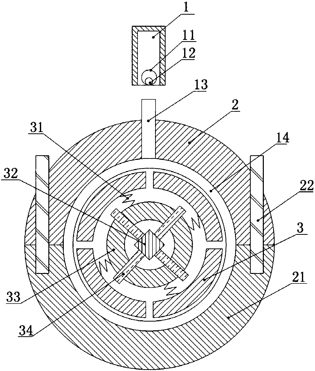
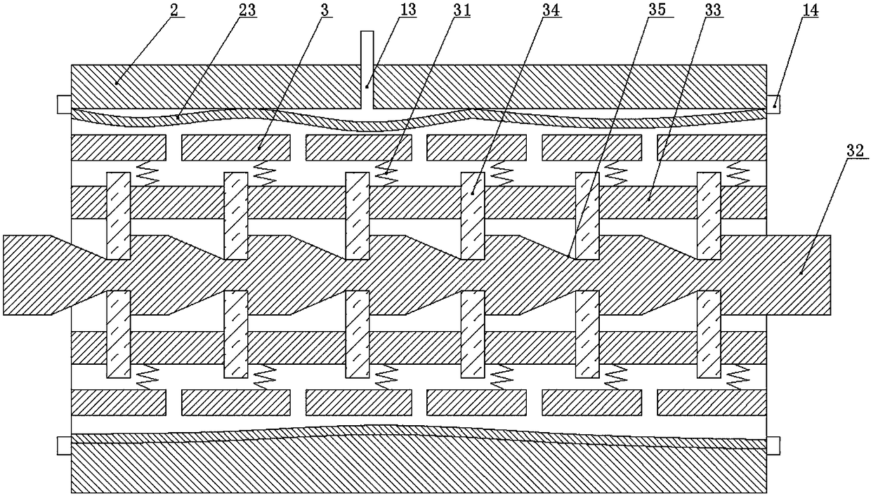
[0021] The reference signs in the accompanying drawings of the description include: placing tube 1, ball 11, bell 12, air outlet pipe 13, ring seal 14, upper fixing plate 2, lower fixing plate 21, bolt 22, pipe fitting 23, top plate 3, spring 31 , Square shaft 32, fixed cylinder 33, push rod 34, groove 35.
[0022] Such as figure 1 and figure 2 As shown, a pipe fitting shaping device includes a fixing mechanism, and the fixing mechanism includes a lower fixing plate 21 and an upper fixing plate 2 installed above the lower fixing plate 21. Both the upper fixing plate 2 and the lower fixing plate 21 are provided with threaded holes. Bolts 22 are threaded in the holes to connect the upper fixing plate 2 and the lower fixing plate 21 . The top of the lower fixing plate 21 is recessed downwards to form the first slot, and the bottom of the upper fixing plate 2 is sunken upwards to for...
PUM
 Abstract
Description
Claims
Application Information