Unlock instant, AI-driven research and patent intelligence for your innovation.
A kind of CNC horizontal lathe equipment
What is Al technical title?
Al technical title is built by PatSnap Al team. It summarizes the technical point description of the patent document.
A horizontal lathe and equipment technology, applied in the field of CNC lathes, can solve the problems of increasing the friction between the nut and the lead screw, increasing the weight of the nut, speeding up the loosening, etc., and achieving the effects of reducing resistance, prolonging service life and reducing friction.
Active Publication Date: 2020-12-18
黑玛智能科技(阳春)有限公司
View PDF4 Cites 0 Cited by
Summary
Abstract
Description
Claims
Application Information
AI Technical Summary
This helps you quickly interpret patents by identifying the three key elements:
Problems solved by technology
Method used
Benefits of technology
Problems solved by technology
[0003] The current CNC horizontal lathe equipment moves the feed system of the tool holder through the screw drive during work. Due to the weight of the feed system of the tool holder, the weight of the nut will be increased during the movement, thereby increasing the distance between the nut and the screw. Friction, to speed up the loosening between the two
Method used
Image
Click on the blue label to locate the original text in one second.
Reading with bidirectional positioning of images and text.
Examples
Embodiment 1
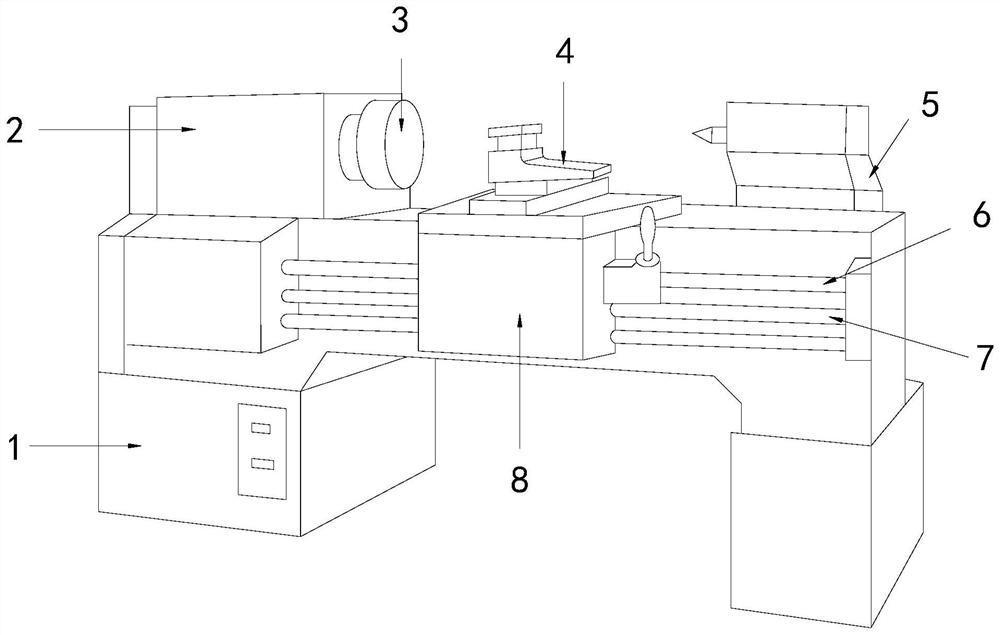
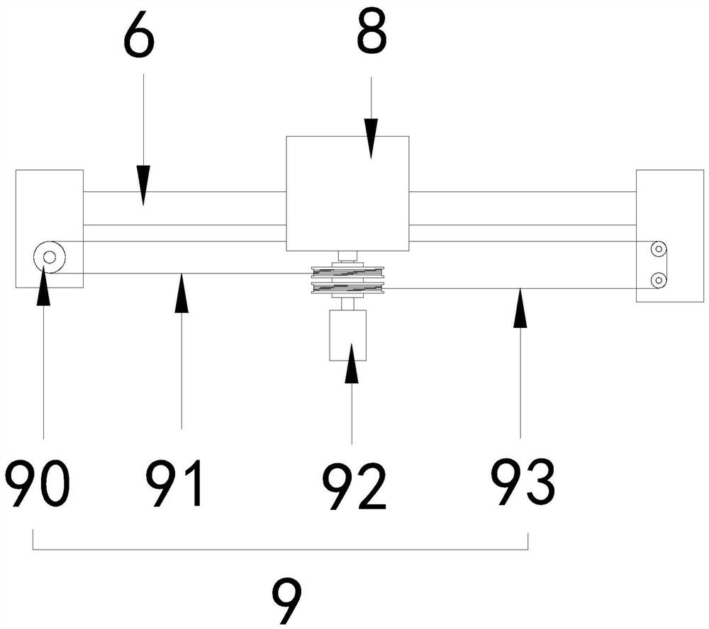
[0027] see Figure 1-3 , the present invention provides a technical solution for CNC horizontal lathe equipment: its structure includes a bed 1, a power box 2, a spindle 3, a tool rest 4, a tailstock 5, a lead screw 6, a feed rod 7, and a tool rest feed system 8 , booster device 9, lead screw 6, feed rod 7 are installed on described bed 1, described tool rest feed system 8 is connected with lead screw 6, feed rod 7 movably, described tool rest feed system 8 tops are arranged There is a tool rest 4, the main shaft 3 is located on the left side of the tool rest 4 and is connected with the power box 2, the power box 2 is fixed on the bed 1, and the right side of the bed 1 is provided with a tailstock 5, so The booster device 9 is connected with the tool post feeding system 8 and is arranged inside the bed 1. The booster device 9 includes a pulley 90, a first stay cord 91, a winding structure 92, and a second stay cord 93. The two sides of the roll structure 92 are respectively c...
Embodiment 2
[0030] see Figure 1-4, the present invention provides a technical solution for CNC horizontal lathe equipment: its structure includes a bed 1, a power box 2, a spindle 3, a tool rest 4, a tailstock 5, a lead screw 6, a feed rod 7, and a tool rest feed system 8 , booster device 9, lead screw 6, feed rod 7 are installed on described bed 1, described tool rest feed system 8 is connected with lead screw 6, feed rod 7 movably, described tool rest feed system 8 tops are arranged There is a tool rest 4, the main shaft 3 is located on the left side of the tool rest 4 and is connected with the power box 2, the power box 2 is fixed on the bed 1, and the right side of the bed 1 is provided with a tailstock 5, so The booster device 9 is connected with the tool post feeding system 8 and is arranged inside the bed 1. The booster device 9 includes a pulley 90, a first stay cord 91, a winding structure 92, and a second stay cord 93. The two sides of the roll structure 92 are respectively co...
PUM
Abstract
The invention discloses numerical control horizontal lathe equipment. The numerical control horizontal lathe equipment structurally comprises a lathe bed, a power box, a main shaft, a tool rest, a tailstock, a lead screw, a polish rod, a tool rest feeding system and a power assisting device, wherein the lead screw and the polish rod are installed on the lathe bed, the tool rest feeding system is movably connected with the lead screw and the polish rod, the tool rest is arranged on the top of the tool rest feeding system, the main shaft is arranged on the left side of the tool rest and is connected with the power box, the power box is fixed on the lathe bed, the tailstock is arranged on the right side of the lathe bed, the power assisting device is connected with the tool rest feeding system and arranged inside the lathe bed, and the power assisting device comprises a pulley, a first pull rope, a winding structure and a second pull rope. The numerical control horizontal lathe equipmenthas the beneficial effects that the moving tool rest feeding system can be assisted by the power assisting device, so that the resistance is reduced, in addition, friction between a nut and the lead screw is reduced, the service life of the nut and the lead screw is prolonged, two movable claws opposite in direction match with a first winding wheel and a second winding wheel so that respective work can be carried out when the two movable claws move in the left direction and the right direction, and mutual interference is avoided.
Description
technical field [0001] The invention relates to a numerically controlled lathe, in particular to a horizontal lathe with a tool rest assisting device. Background technique [0002] CNC lathes, also known as CNC lathes, or computer numerical control lathes, are currently the most widely used and widely covered CNC machine tools in China, accounting for about 25% of the total number of CNC machine tools. It is a mechatronic product integrated with multiple technologies such as microelectronics, information, etc. It is a workhorse with the advantages of high precision, high efficiency, high automation and high flexibility in mechanical manufacturing equipment. [0003] The current CNC horizontal lathe equipment moves the feed system of the tool holder through the screw drive during work. Due to the weight of the feed system of the tool holder, the weight of the nut will be increased during the movement, thereby increasing the distance between the nut and the screw. Friction, t...
Claims
Application Information
Patent Timeline
Application Date:The date an application was filed.
Publication Date:The date a patent or application was officially published.
First Publication Date:The earliest publication date of a patent with the same application number.
Issue Date:Publication date of the patent grant document.
PCT Entry Date:The Entry date of PCT National Phase.
Estimated Expiry Date:The statutory expiry date of a patent right according to the Patent Law, and it is the longest term of protection that the patent right can achieve without the termination of the patent right due to other reasons(Term extension factor has been taken into account ).
Invalid Date:Actual expiry date is based on effective date or publication date of legal transaction data of invalid patent.
