Pin removal device

A pin device and nail head technology, which is applied in the field of aircraft manufacturing tools, can solve problems such as pin difficulty, pin deformation, and reduced production efficiency, and achieve the effect of easy pin removal

Pending Publication Date: 2020-06-05
COMAC +1
View PDF0 Cites 0 Cited by
  • Summary
  • Abstract
  • Description
  • Claims
  • Application Information

AI Technical Summary

Problems solved by technology

Due to the tight fit between the pins and the mold and parts after insertion, and the large number of pins used, it is difficult to remove the pins manually, and it is easy to deform the pins, thereby greatly reducing production efficiency

Method used


Image

  • Pin removal device
  • Pin removal device
  • Pin removal device

Examples


Embodiment Construction

[0022] In order to make the technical problems solved by the present invention, the technical solutions adopted, and the technical effects achieved more clearly, the technical solutions of the embodiments of the present invention will be described in further detail below in conjunction with the accompanying drawings. Obviously, the described embodiments are only the present invention. Some embodiments, not all embodiments. Based on the embodiments of the present invention, all other embodiments obtained by those skilled in the art without creative work shall fall within the protection scope of the present invention.

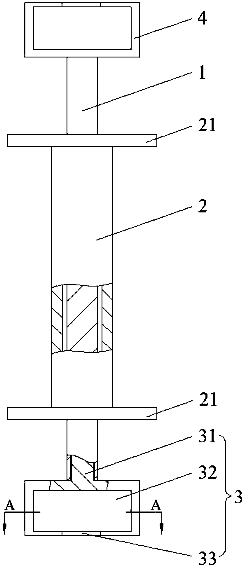
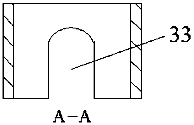
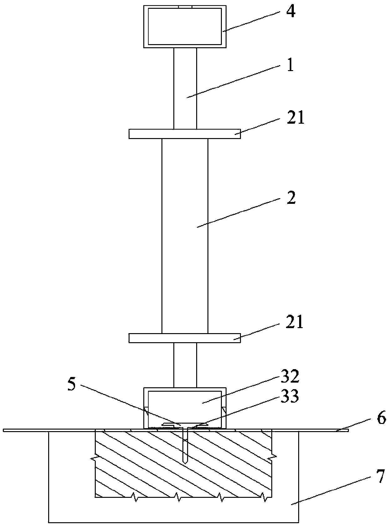
[0023] Such as figure 1 As shown, it is a schematic structural diagram of the pin taking device of this embodiment. The pin removing device includes a connecting rod 1, a sliding part that moves and sleeves along the axial direction of the connecting rod 1, a nail puller 3 and abutting parts 4 respectively provided at both ends of the connecting rod 1, and a handle ...


PUM


Abstract

The invention discloses a pin removal device, and belongs to the field of aircraft manufacturing tools. The pin removal device comprises a connecting rod, a sliding part, a pin pulling head and an abutting part, wherein the sliding part moves along an axial direction of the connecting rod; the pin pulling head and the abutting part are arranged at two ends of the connecting rod respectively; the sliding part can be abutted to the abutting part; the pin pulling head is provided with a clamping part; and the clamping part can be clamped with a lower end face of the head of a pin. When the sliding part moves along the connecting rod and collides with the abutting part, the pin pulling head clamped with the lower end of the pin head generates upward force on the pin, so that the pin can be pulled out easily.

Description

Technical field [0001] The invention relates to the field of tools for aircraft manufacturing, in particular to a pin taking device. Background technique [0002] The production of aircraft parts requires the guarantee of molds. Before the upper and lower molds of the aircraft parts work together, the parts need to be accurately placed on the mold. Pins are generally used to ensure accurate positioning of the parts on the mold. The mold and the part are provided with a plurality of positioning holes corresponding to each other, the part is placed on the mold, and the pins are inserted into the positioning holes of the part and the mold in turn to complete the positioning of the part. [0003] There is a gap between the lower end surface of the pin head and the upper surface of the part. In the prior art, a crowbar is generally inserted into the gap between the pin head and the part, and the crowbar is manually moved to pull out the pin. Since the pin fits tightly with the mold a...

Claims


Application Information

Patent Timeline
Patent Type & Authority Applications(China)
IPC IPC(8): B25B27/02
CPCB25B27/02
Inventor 胡敏徐友钧黄璐张嘉沂宋晓俊颜禧涛
Owner COMAC
Why Eureka
Try Eureka