
Modular hand grip and rail assembly for firearms

Active Publication Date: 2007-05-15
TROY STEPHEN P JR
View PDF12 Cites 171 Cited by
  • Summary
  • Abstract
  • Description
  • Claims
  • Application Information

AI Technical Summary

Benefits of technology

[0009]Briefly, to achieve the desired objects of the present invention in accordance with a preferred embodiment thereof, provided is a modular hand grip for use on a firearm and for engaging a barrel nut of the firearm. The barrel nut includes a cylindrical portion terminating at a forwardly directed end with a radially outwardly directed flange. The hand grip includes an upper portion having a forward end, a rearward end, an inner surface and an outer surface. A groove is formed in the inner surface o

Problems solved by technology

Several problems are prevalent in the firearms industry with respect to hand grip and rail assemblies.
Many firearms are operated as automatic or semiautomatic and have a tendency to heat extensively so that handgrips attached directly to the barrel can produce hand burns for the operator if great care is not taken.
In addition, anything attached directly to the barrel of a firearm can have a tendency to alter the barrel slightly and any alterations can adversely affect the accuracy of the firearm.

Method used


Image

  • Modular hand grip and rail assembly for firearms
  • Modular hand grip and rail assembly for firearms
  • Modular hand grip and rail assembly for firearms

Examples


Embodiment Construction

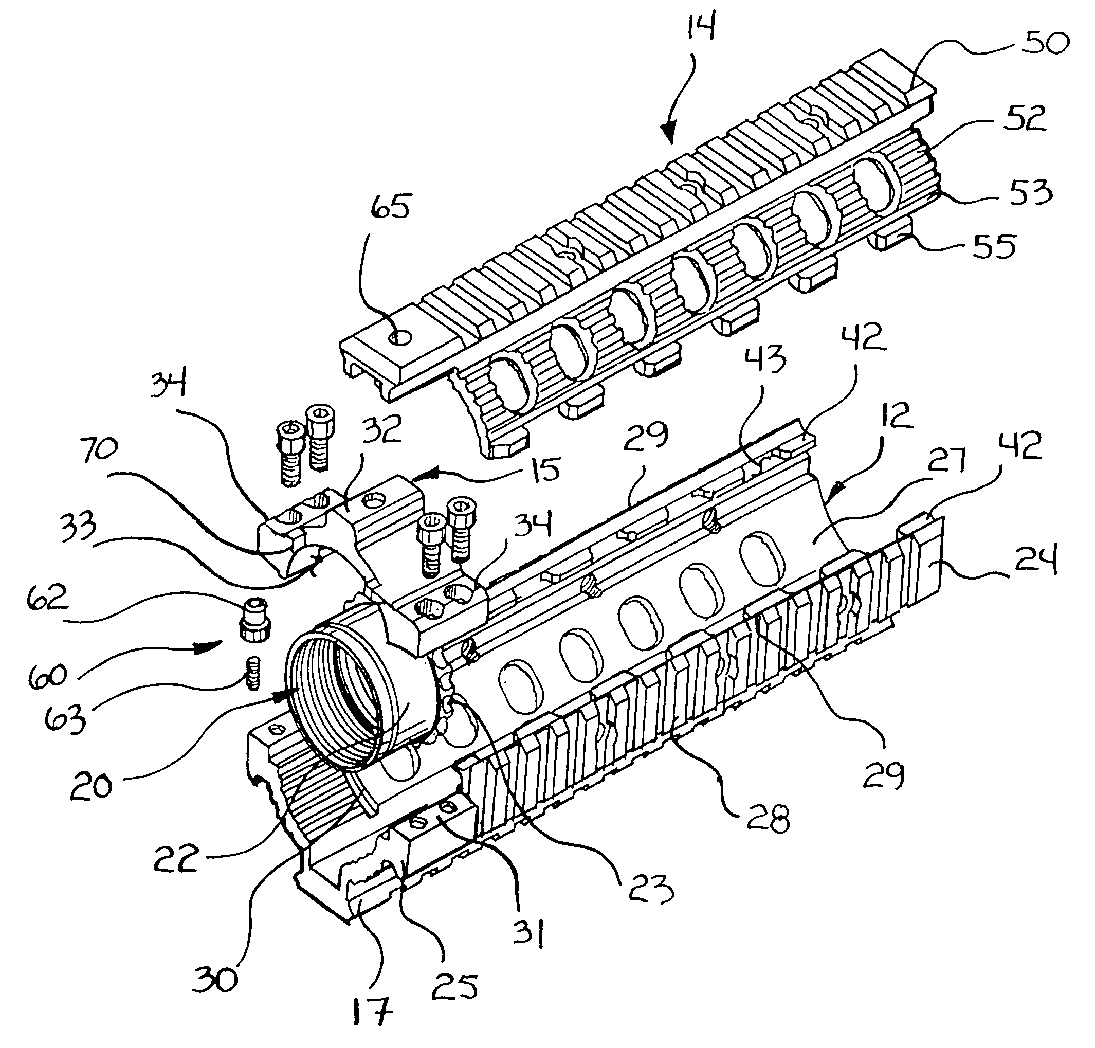
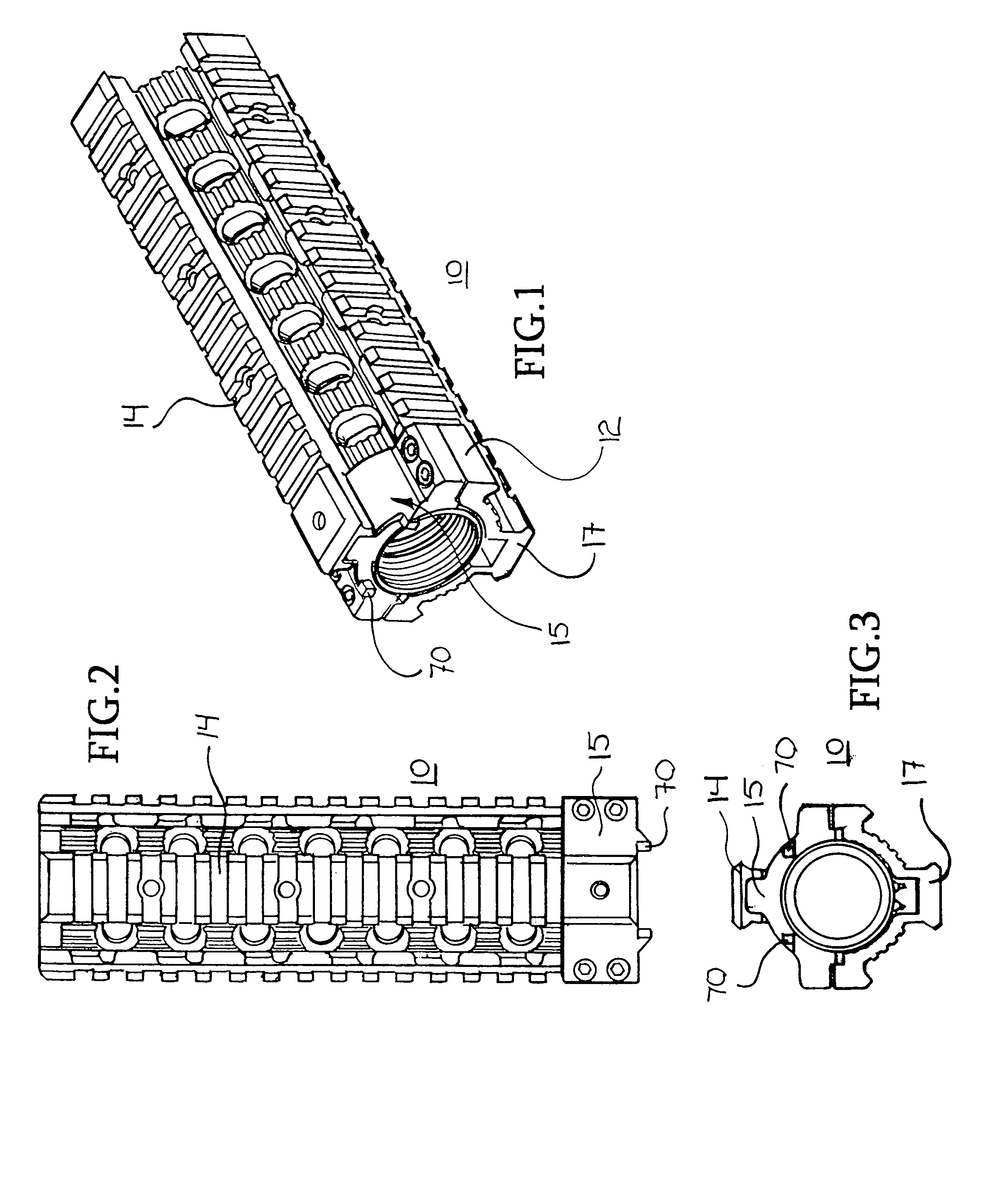
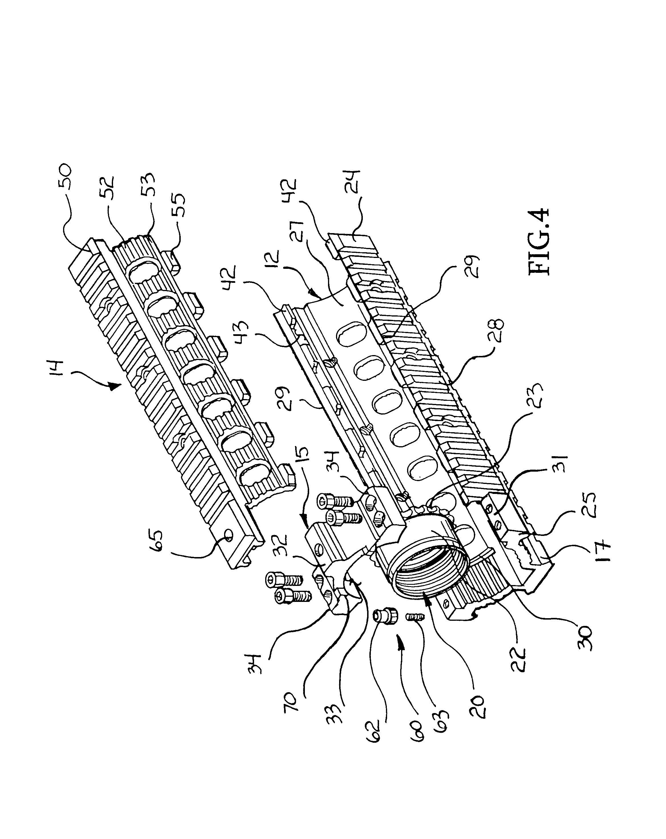
[0020]Turning now to the drawings in which like reference characters indicate corresponding elements throughout the several views, attention is directed to FIGS. 1–3 which illustrate a modular hand grip according to the present invention, generally designated 10. Modular hand grip 10 includes three main elements, an upper portion 12, a lower portion 14, and a coupling assembly 15. Upper portion 12 can, and preferably does include a rail 17 provided to permit the coupling of additional accessory devices. Modular hand grip 10 is removably coupled to the fore-end of a firearm, providing a grip, rail, and rail alignment assembly.

[0021]With reference to FIGS. 4, 5, and 6, modular hand grip 10 is coupled to a firearm 100 (illustrated in FIG. 7) through engagement with a barrel nut 20. Firearm 100 includes a receiver 110 and a barrel 112. For purposes of this description, the term forwardly is intended to refer to the direction toward a muzzle 114 of firearm 100, and rearwardly is directed...


PUM


Abstract

A modular hand grip for use on a firearm, the modular hand grip includes an upper portion, a lower portion and a coupling assembly. A rearward end of the upper portion is configured to engage a top portion of a barrel nut. Lug rails having gaps therein project from an inner surface of the upper portion at opposing sides and proximate edges thereof. The coupling assembly is engagable with a bottom portion of the barrel nut and is attached to the rearward end of the upper portion. The lower portion has opposing side sections, each terminating at an edge. A plurality of spaced apart lugs extend from each edge and are receivable in the gaps in the lug rails of the upper portion and are translatable in one of a forward direction and a rearward direction positioning the lugs under the lug rails.

Description

CROSS-REFERENCE TO RELATED APPLICATION[0001]This application claims the benefit of U.S. Provisional Application No. 60 / 652,035, filed 11 Feb. 2005.FIELD OF THE INVENTION[0002]This invention relates to firearms accessories.[0003]More particularly, the present invention relates to hand grip and rail accessories.BACKGROUND OF THE INVENTION[0004]It is understood that hand-held firearms require some type of handgrip so that the operator can hold the firearm as it is fired. Also, many accessories are available that aid in the proper and / or enhanced operation of firearms and some type of platform or mounting structure is generally provided or available as an accessory for this function. Several problems are prevalent in the firearms industry with respect to hand grip and rail assemblies. Many firearms are operated as automatic or semiautomatic and have a tendency to heat extensively so that handgrips attached directly to the barrel can produce hand burns for the operator if great care is n...

Claims


Application Information

Patent Timeline
IPC IPC(8): F41C23/00
CPCF41C23/16F41G11/003
Inventor TROY, STEPHEN P.
Owner TROY STEPHEN P JR
Learn More