Circular stirring concrete stirrer

A concrete mixer and circulating mixing technology, which is applied to cement mixing devices, clay preparation devices, chemical instruments and methods, etc., can solve the problems of inability to mix a large amount of concrete, low discharge efficiency, and insufficiency, and achieve rapid mixing operations. even effect

Active Publication Date: 2020-06-05
ZHEJIANG GUANGSHA COLLEGE OF APPLIED CONSTRTECH
View PDF8 Cites 2 Cited by
  • Summary
  • Abstract
  • Description
  • Claims
  • Application Information

AI Technical Summary

Problems solved by technology

However, when the volume of the mixing tank is much larger than that of the rotary mixing mechanism, the mixer has a low discharge efficiency. It cannot mix a large amount of concrete when the intensity of the concrete mixing operation in the early stage is high, and it cannot perform more detailed mixing in the mixing operation of the concrete in the middle and later stages. , and it is not convenient to control the mixing degree of concrete, and it is prone to local over-mixing or insufficient mixing effect

Method used


Image

  • Circular stirring concrete stirrer
  • Circular stirring concrete stirrer
  • Circular stirring concrete stirrer

Examples


specific Embodiment approach 1

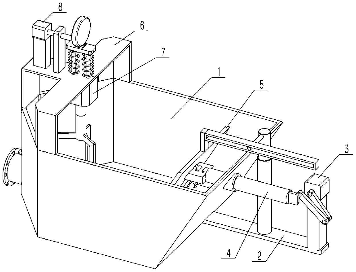
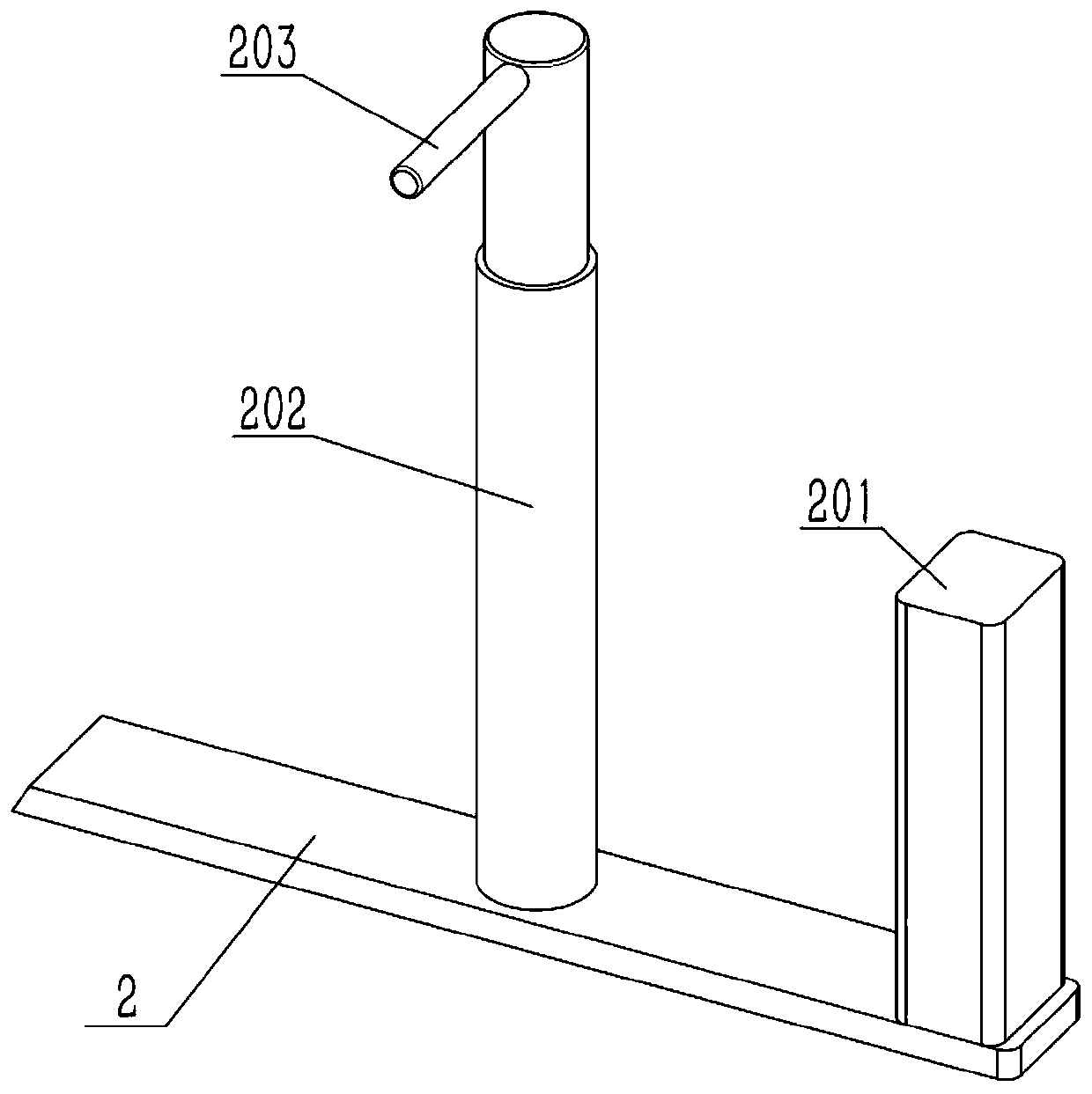
[0030] Such as Figure 1-9 As shown, a circulating mixing concrete mixer includes a motor II7, a main shaft 705, a stirring blade 706 and a pounding blade 707. The output shaft of the motor II7 is fixedly connected to the main shaft 705, and the lower side of the main shaft 705 is provided with a stirring blade 706. The lower end of leaf 706 is fixedly connected with stamping leaf 707, and the cross-sectional area of ​​stamping leaf 707 is greater than the cross-sectional area of ​​the junction of stirring leaf 706 and stamping leaf 707, and stirring leaf 706 can drive stamping leaf 707 to move up and down when stirring and preparing concrete, and stamping leaf The lowest position of the 707 movement reaches the bottom of the prepared concrete. The stirring blade 706 is driven by the motor Ⅱ7 to realize the rotation. During this action, the stirring blade 706 is controlled to move up and down, and then the stirring blade 706 is used to drive the pounding blade 707 to move up a...

specific Embodiment approach 2

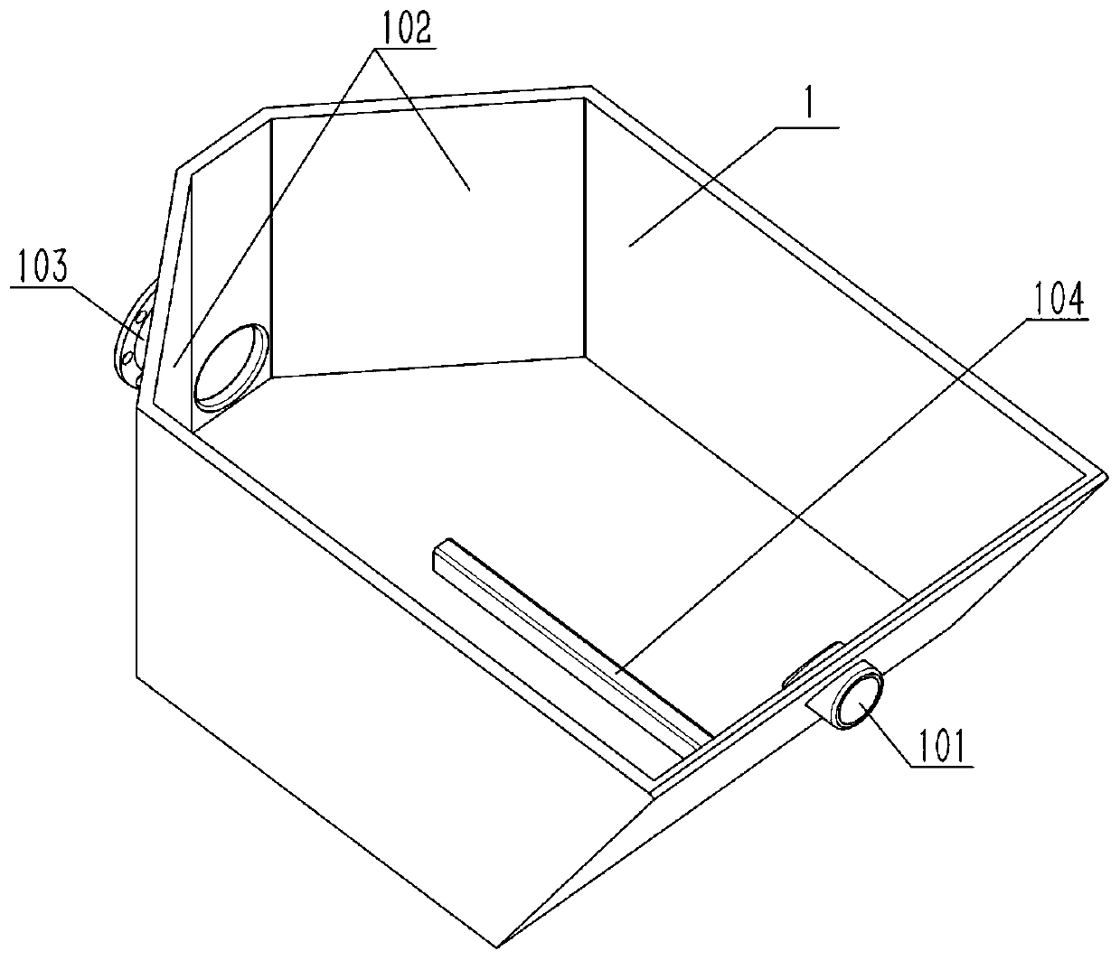
[0032] Such as Figure 1-9 As shown, the circulating mixing concrete mixer also includes a processing box 1, a frame 6, a reset rod 701, a compression spring 702 and a flat plate 703, the upper end of the processing box 1 is fixed to the frame 6, and the upper end of the motor II 7 is fixed to two Reset lever 701, two reset levers 701 are slidably connected on the frame 6, the flat plate 703 is fixedly connected to the upper ends of the two reset levers 701, and the compression spring 702 is located between the flat plate 703 and the frame 6, by controlling the up and down movement of the flat plate 703 Drive the stirring blade 706 to move up and down. The flat plate 703 is convenient to be connected with mechanisms such as electric telescopic rods to realize up and down movement, and is also convenient to realize manual stepping to realize up and down movement. The compression spring 702 can be set by observing the rebound of the flat plate 703. If the rebound is smooth, it m...

specific Embodiment approach 3

[0034] Such as Figure 1-9 As shown, the circulating mixing concrete mixer also includes a base II601, a bearing with seat 602, a wheel 704, a motor III8 and an eccentric wheel 801, the base II601 is fixed on the frame 6, and the motor III8 is fixed on the base II601 Above, the output shaft of the motor III8 is rotatably connected to the bearing 602 with seat, the eccentric position of the eccentric wheel 801 is fixedly connected to the output shaft of the motor III8, the eccentric wheel 801 is in contact with the wheel 704, and the wheel 704 is rotatably connected to the flat plate 703. The rotation of the eccentric wheel 801 drives the wheel 704 to move up and down to realize the up and down movement of the flat plate 703 . Start the motor Ⅲ8, the output shaft of the motor Ⅲ8 drives the eccentric wheel 801 to rotate, and the eccentric wheel 801 can press the wheel 704 to move downward once every time the eccentric wheel 801 rotates, so that the up and down reciprocating moti...


PUM


Abstract

The invention relates to the field of concrete preparation, in particular to a circular stirring concrete stirrer. The circular stirring concrete stirrer comprises a motor II, a spindle, stirring blades and ramming blades. According to different concrete mixing degrees, different stirring modes are employed, so that the stirring efficiency and the stirring effect are improved and the service lifeof rotary stirring equipment is prolonged. In an early stirring operation, a push-stirring plate moves left and right to a great extent for large-scaled initial stirring, and meanwhile, a rotary stirring mechanism composed of the stirring blades and the ramming blades stir concrete at fixed points, so that the work strength of the rotary stirring mechanism in the early stage is reduced. In the middle and later periods of stirring operation, the push-stirring plate moves leftward to push the initially stirred concrete to the rotary stirring mechanism to be stirred more finely, and then the push-stirring plate is elevated to move rightward, so that the finely stirred concrete flows back to the right side naturally to be circulated. So repeatedly, it is convenient to stir the concrete quicklyin a large volume container and the stirring effect is uniform.

Description

technical field [0001] The invention relates to the field of concrete preparation, in particular to a circulating mixing concrete mixer. Background technique [0002] For example, the publication number is CN206551220U a kind of concrete mixer, which includes a mixing bucket, and also includes a rotating drum vertically arranged in the mixing drum with openings at both ends, a first helical blade fixed on the inner wall of the rotating drum, and used to drive the mixing drum. The first power part for rotating the rotating drum, the stirring shaft inserted in the rotating drum, the second helical blade fixed on the stirring shaft, the second power part for driving the rotating shaft, the rotating The rotation direction of the drum is opposite to the rotation direction of the stirring shaft. The utility model has the following advantages and effects: the first power part is used to drive the rotating drum, and the second power part is used to drive the stirring shaft to rotat...

Claims


Application Information

Patent Timeline
Patent Type & Authority Applications(China)
IPC IPC(8): B28C5/16
CPCB28C5/16
Inventor 王瑜玲王春福
Owner ZHEJIANG GUANGSHA COLLEGE OF APPLIED CONSTRTECH
Why Eureka
Try Eureka