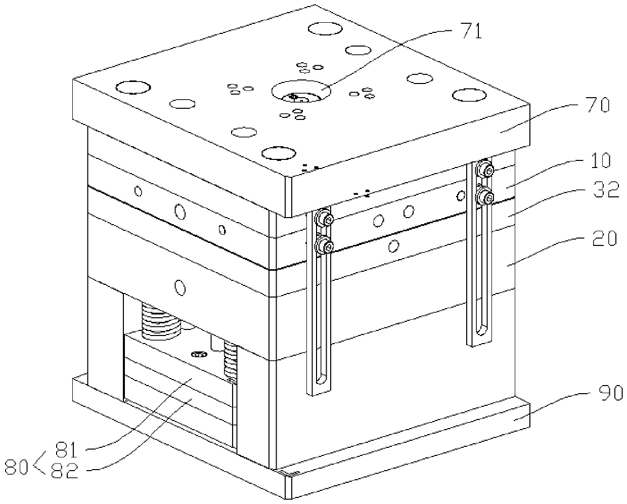
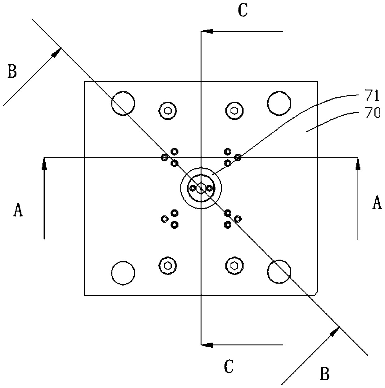
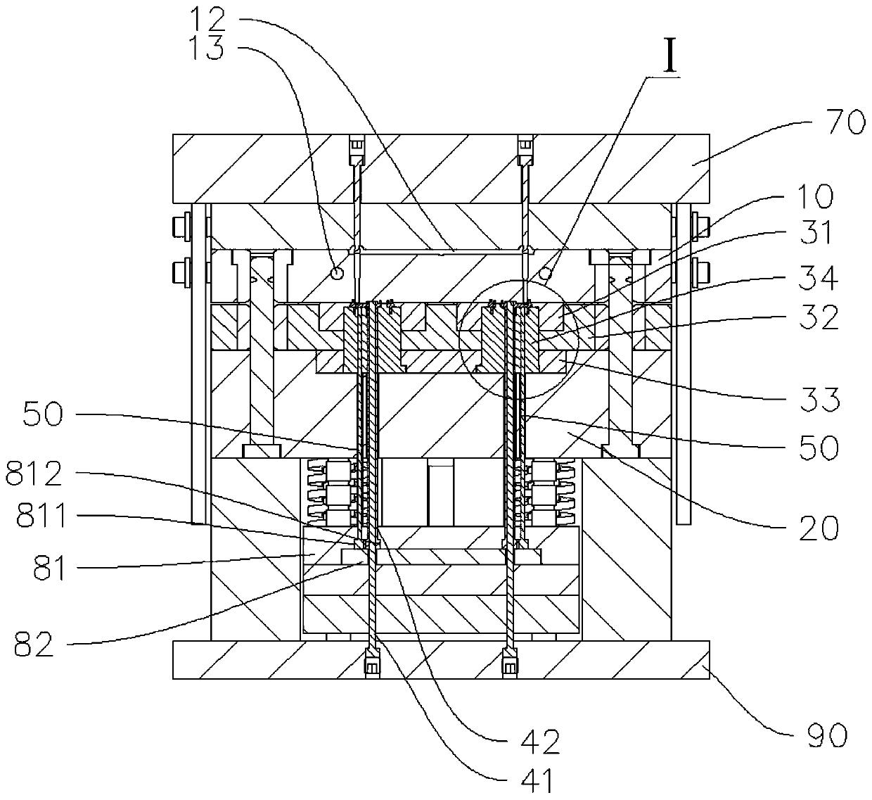
Bevel gear injection mold and bevel gear

A technology for injection molds and helical gears, applied in gears, belts/chains/gears, household appliances, etc., can solve problems such as damage to helical gears, affecting the rotation of helical gears, and unsmooth demoulding.

Inactive Publication Date: 2020-06-05
东莞力浦精密电子有限公司
View PDF4 Cites 1 Cited by
  • Summary
  • Abstract
  • Description
  • Claims
  • Application Information

AI Technical Summary

Problems solved by technology

[0002] At present, in the process of forming helical gears with injection molds, it is difficult to demould the helical gears. The structure of the

Method used


Image

  • Bevel gear injection mold and bevel gear
  • Bevel gear injection mold and bevel gear
  • Bevel gear injection mold and bevel gear

Examples


Embodiment Construction

[0043] This part will describe the specific embodiment of the present invention in detail, and the preferred embodiment of the present invention is shown in the accompanying drawings, and the function of the accompanying drawings is to supplement the description of the text part of the specification with figures, so that the present invention can be intuitively and vividly understood Each technical feature and the overall technical solution, but it should not be construed as a limitation on the protection scope of the present invention.

[0044] In the description of the present invention, if it involves orientation description, for example, the orientation or positional relationship indicated by "upper", "lower", "front", "back", "left", "right" etc. is based on the The orientation or positional relationship is only for the convenience of describing the present invention and simplifying the description, but does not indicate or imply that the device or element referred to must...


PUM


Abstract

The invention relates to the technical field of molds, and provides a bevel gear injection mold and a bevel gear. Through the arrangement of a mold core, an ejector pin, a push rod, a first mold plateand a second mold plate, during demolding, after the first mold plate is lifted, a push plate is pushed upwards firstly, and meanwhile, a forming plate and a product are pushed away from a bearing piece together; and therefore, a bevel gear product is degummed from a second concave cavity of the bearing piece and is separated from an axis rod of the push rod, and the second concave cavity is prevented from hindering the rotation of the bevel gear product when the bevel gear is disengaged. The product is ejected twice through a sleeve of the push rod, so that the tooth removal of the bevel gear product is realized, in the process, due to the fact that the bottom of the product is degummed, rotation is not affected during tooth disengaging, when the product is subjected to tooth disengaging, the product can rotate relative to the forming plate, the bevel gear rotates along an inner gear ring of the forming plate to be subjected to tooth disengaging, and product demolding is achieved.

Description

technical field [0001] The invention relates to the technical field of moulds, in particular to a helical gear injection mold and helical gears. Background technique [0002] At present, in the process of forming helical gears with injection molds, it is difficult to remove the helical gears from the mold. The structure of the mold may easily affect the rotation of the helical gears during demoulding, resulting in unsmooth demoulding and even damage to the helical gears. Contents of the invention [0003] The present invention aims to solve one of the technical problems mentioned above. According to an embodiment of the present invention, there is provided a helical gear injection mold, which can be used to mold injection molded parts with an internal gear ring, and the mold processing is less difficult, less time-consuming and helps to improve the precision of molded products. [0004] The embodiment of the present invention also provides a helical gear injection-molded ...

Claims


Application Information

Patent Timeline
IPC IPC(8): B29C45/40B29C45/26F16H55/17B29L15/00
CPCB29C45/2602B29C45/4005B29L2015/003F16H55/17
Inventor 陈炜煌钟达礼
Owner 东莞力浦精密电子有限公司
Why Eureka
Try Eureka