Self-locking type amplifying lifting mechanism

A lifting mechanism and self-locking technology, applied in the field of self-locking amplifying lifting mechanism, can solve the problems of high cost and complex hydraulic drive system, shorten the length of the tie rod, reduce the weight of the mechanism, and improve the lifting stability. Effect

Pending Publication Date: 2020-06-05
LIUZHOU CHANGHONG DIGITAL CONTROL MACHINE TOOL
View PDF0 Cites 0 Cited by
  • Summary
  • Abstract
  • Description
  • Claims
  • Application Information

AI Technical Summary

Problems solved by technology

At the same time, in order to maintain the state of the lifting mechanism at any position, a special pressure-holding unit needs to be installed in the oil cylinder and the hydraulic drive system, so the hydraulic drive system will be more complicated and costly

Method used


Image

  • Self-locking type amplifying lifting mechanism
  • Self-locking type amplifying lifting mechanism
  • Self-locking type amplifying lifting mechanism

Examples


Embodiment Construction

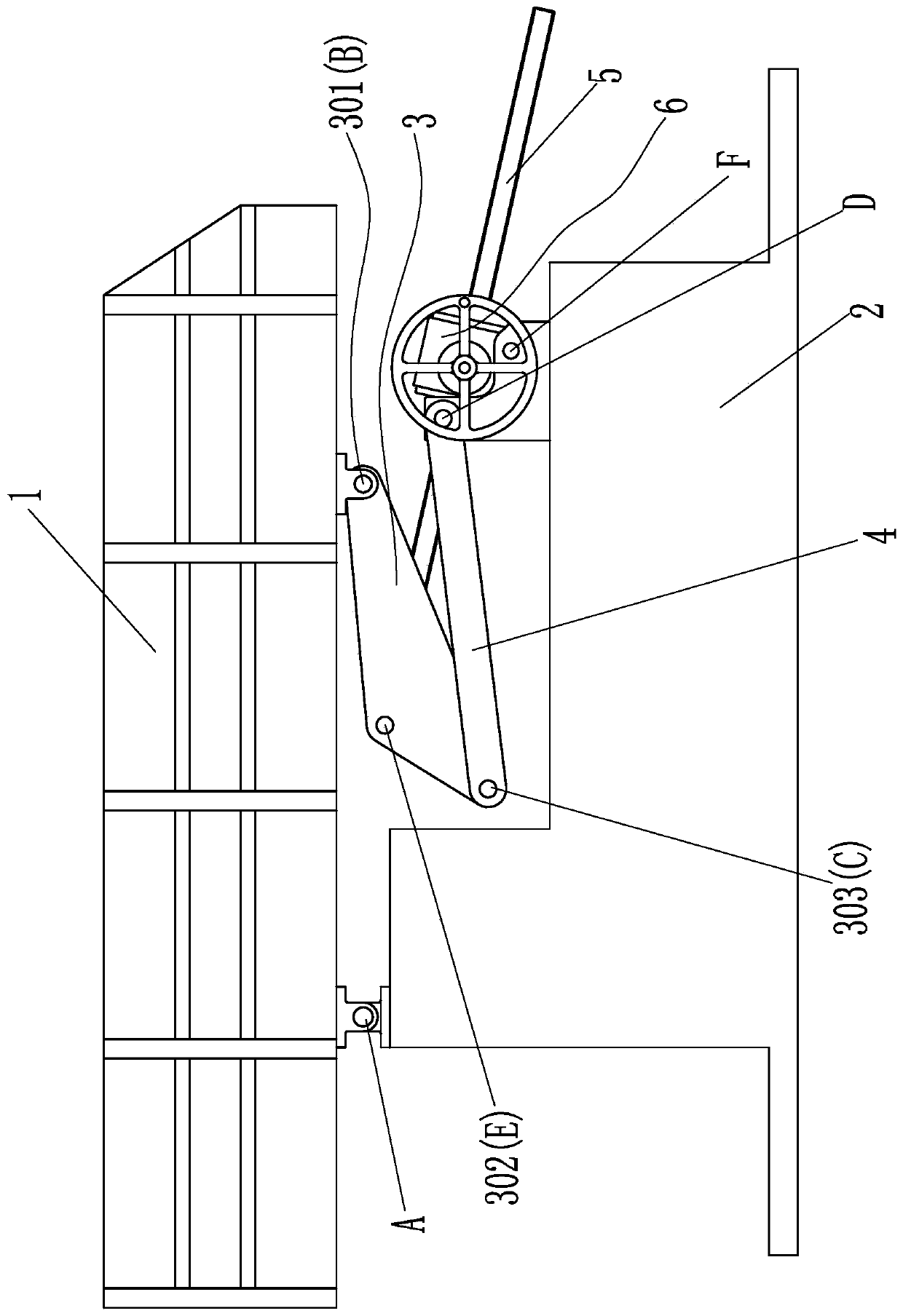
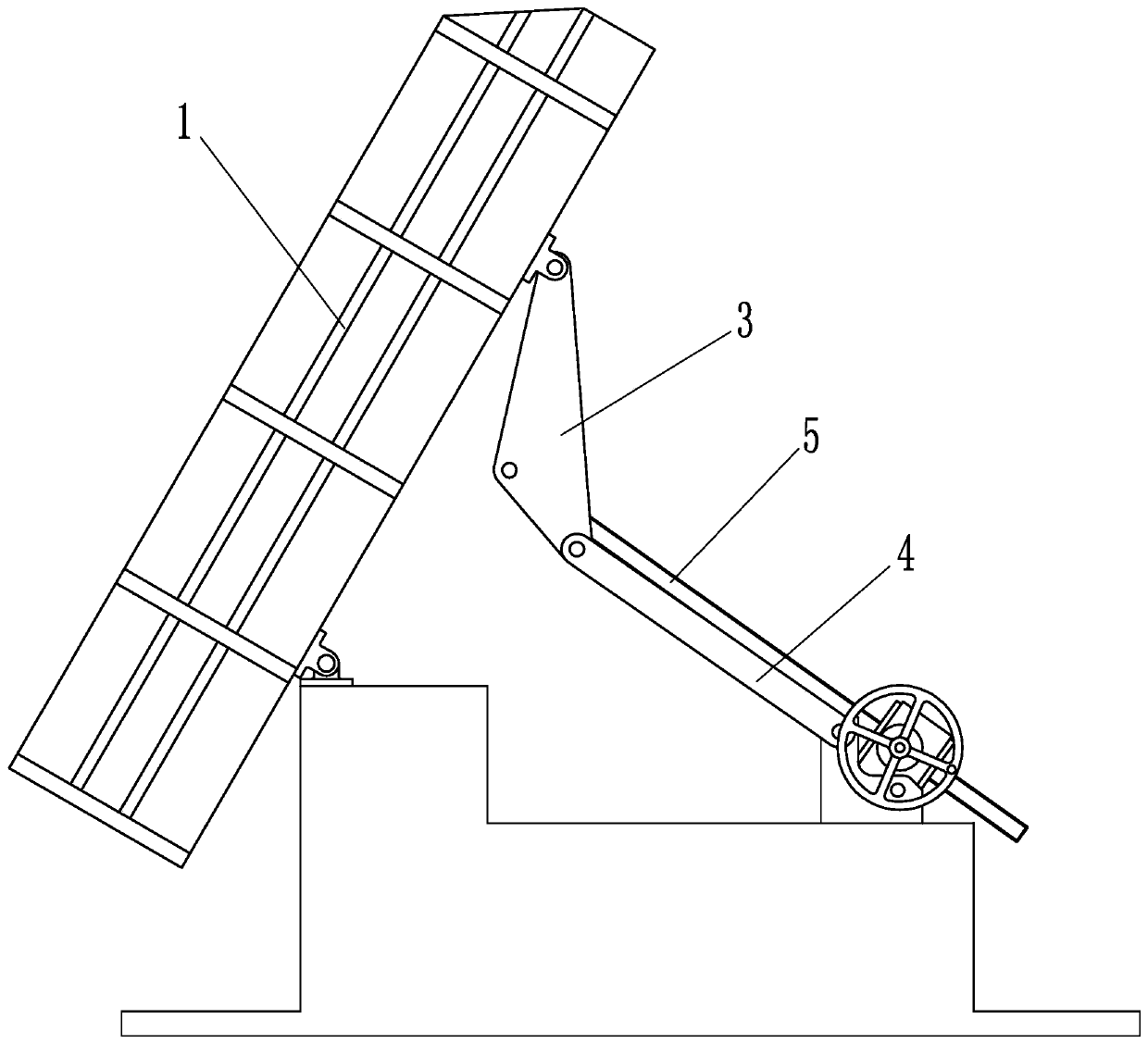
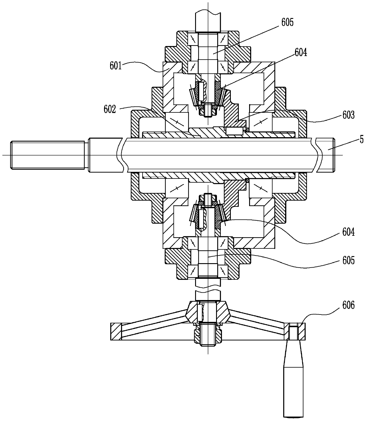
[0014] Such as Figure 1 to Figure 3 As shown, the self-locking enlarged lifting mechanism of the present invention includes a bracket 1 , a lift and a base 2 . Bracket 1 is used to lift objects. The rear end of the bottom end of bracket 1 is hinged with the rear end of base 2. The hinge is the first hinge point A. The lift is connected between the front end of base 2 and the front end of bracket 1. between. The lift comprises a reduction box 6, two triangular arms 3, two pull rods 4 and a leading screw 5. The two triangular arms 3 are relatively arranged at the bottom of the bracket 1, and three hinge points are respectively set at the three corners of each triangular arm 3, and the three hinge points are respectively hinge point I301, hinge point II302, and hinge point III303. The hinge points I301 of the two triangular arms 3 are respectively hinged with the front side of the bottom end of the bracket 1, and this hinge point is the second hinge point B. The hinge points ...


PUM


Abstract

The invention discloses a self-locking type amplifying lifting mechanism. The mechanism comprises a bracket, a lifting machine and a base; the rear side of the bottom end of the bracket is hinged to the rear end of the base; the lifting machine is connected between the front end of the base and the front side of the bottom end of the bracket; the lifting machine comprises a reduction gearbox, twotriangular arms, two pull rods and a screw rod; the triangular arms are oppositely arranged at the bottom of the bracket, three hinge points are arranged at the three corners of each triangular arm, the hinge points I of the two triangular arms are hinged to the front side of the bottom end of the bracket correspondingly, and the hinge points II of the two triangular arms are connected with each other through a shaft; the reduction gearbox is hinged to the front end of the base, the reduction gearbox comprises a box body and a nut, the two ends of the nut are arranged in the box body through bearings, and a rotating mechanism for driving the nut to rotate is arranged on the box body; the screw rod is screwed in an internal thread of the nut of the reduction gearbox, and the rear end of thescrew rod is hinged to the shaft between the hinge points II of the two triangular arms through a connecting device; and the front ends of the pull rods are hinged to the front end of the base, and the rear ends of the pull rods are hinged to the hinge points III of the triangular arms correspondingly.

Description

technical field [0001] The invention relates to a lifting mechanism, in particular to a self-locking enlarged lifting mechanism. Background technique [0002] At present, most construction machinery lifting mechanisms on the market are cylinder-connecting-rod combined lifting mechanisms or cylinder direct-push lifting mechanisms. What they have in common is that a hydraulic drive system is required to realize the expansion and contraction of the oil cylinder, thereby driving the lift. mechanism. At the same time, in order to maintain the state of the lifting mechanism at any position, a special pressure maintaining unit needs to be provided in the oil cylinder and the hydraulic drive system, so the hydraulic drive system will be more complicated and costly. Contents of the invention [0003] The object of the present invention is to address the defects of the above-mentioned prior art, and provide a self-locking enlarged lifting mechanism that can simplify the lifting mec...

Claims


Application Information

Patent Timeline
IPC IPC(8): B66F7/22B66F7/28
CPCB66F7/22B66F7/28
Inventor 梁飞龙朱江平张昌德李勇梁德广祝平波唐群智
Owner LIUZHOU CHANGHONG DIGITAL CONTROL MACHINE TOOL
Why Eureka
Try Eureka