Pneumatic lifting trolley

A pneumatic lifting and trolley technology, which is applied in the direction of lifting frame, lifting device, roller table, etc., can solve the problems of low automatic intelligence, poor aesthetics, and single transportation, so as to improve the stability of lifting, prevent left and right shaking, and solve manual problems. The effect of stacking

Inactive Publication Date: 2019-08-30
十堰丰凯机电工程有限公司
View PDF1 Cites 10 Cited by
  • Summary
  • Abstract
  • Description
  • Claims
  • Application Information

AI Technical Summary

Problems solved by technology

[0005] The purpose of the present invention is to provide a pneumatic lifting trolley to solve the problems of single material conveyin

Method used


Image

  • Pneumatic lifting trolley
  • Pneumatic lifting trolley
  • Pneumatic lifting trolley

Examples


Embodiment

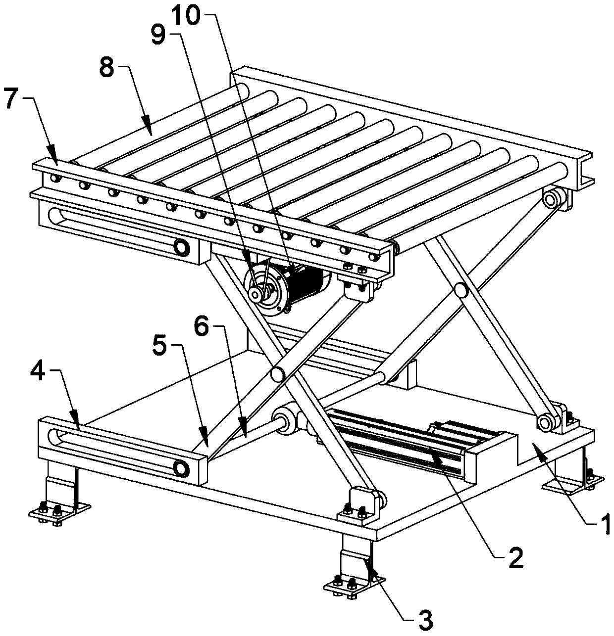
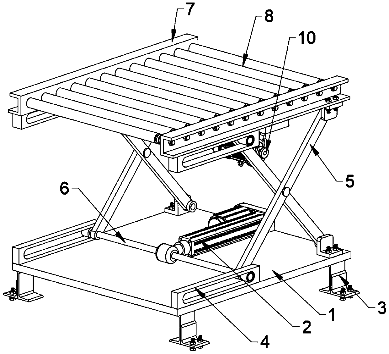
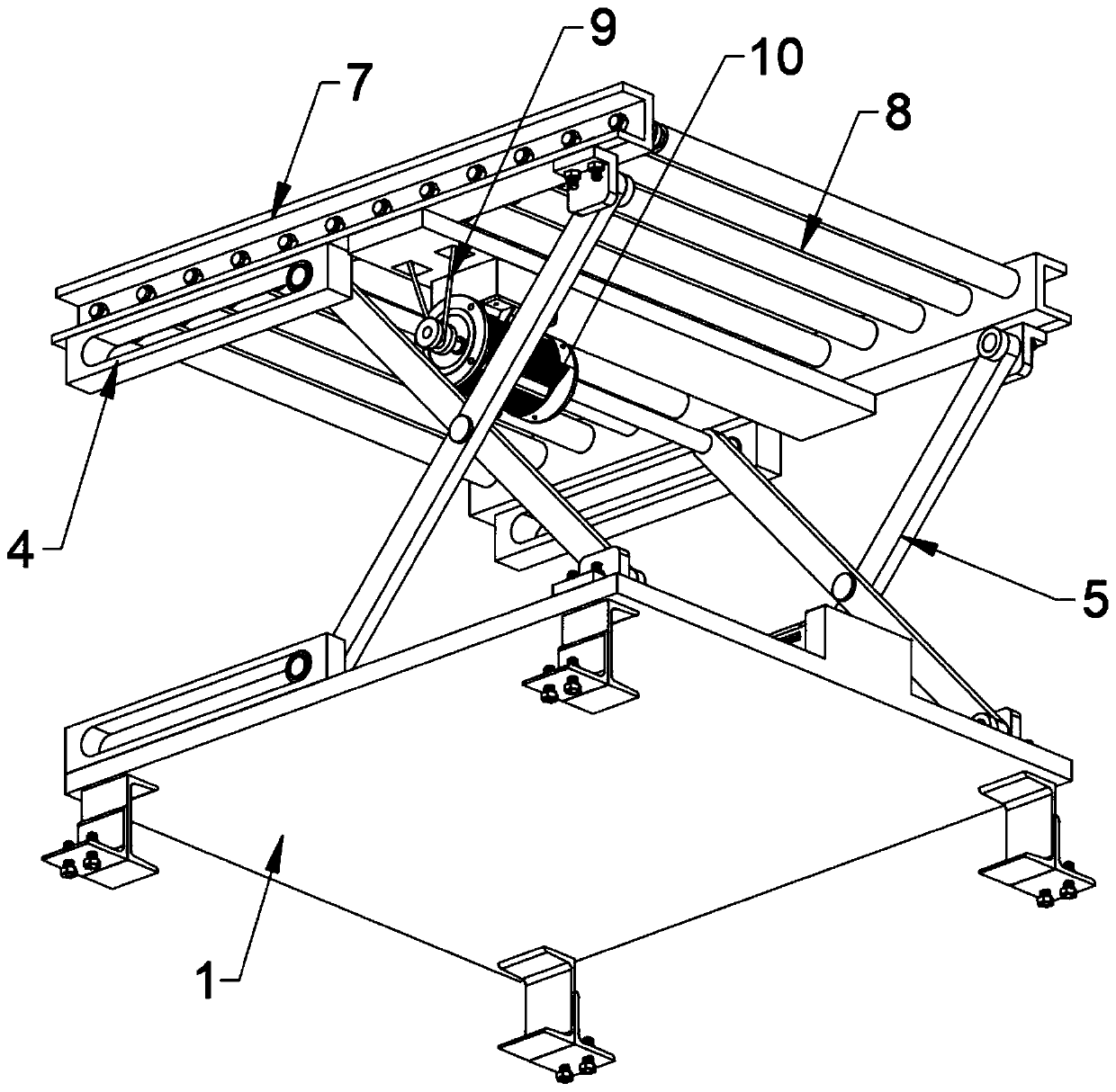
[0033] as attached figure 1 to attach Figure 7 Shown:

[0034] The invention provides a pneumatic lifting trolley, comprising: a device base 1, a cylinder 2, a fixing seat 3, a yoke limit chute 4, a supporting yoke 5, a yoke connecting shaft 6, a shield 7, and a roller assembly 8. The transmission rope 9 and the drive motor 10; the four corners of the lower side of the base 1 of the device are welded with a fixed seat 3, and the fixed seat 3 is fixed and installed on the fixed platform through expansion bolts; the shield 7 is supported by the support fork 5 is connected to the base 1 of the device, and a roller assembly 8 is installed between the two shields 7; the support yoke 5 is designed in an X-shaped structure, and the middle of each set of support yoke 5 is rotatably connected by a rotating shaft.

[0035] Wherein, the upper middle position of the device base 1 is bolted with a cylinder 2, and the front end of the push rod of the cylinder 2 is set on the outside of t...


PUM


Abstract

The invention relates to a pneumatic lifting trolley. The pneumatic lifting trolley comprises a device pedestal, an air cylinder, fixed bases, a fork arm limiting sliding groove, supporting fork arms,a fork arm connecting shaft, protective covers, a roller assembly, a transmission rope and a driving motor; the fixed bases are welded at the four corners of the lower side of the device pedestal andare fixedly arranged on a fixed platform through expansion bolts; the protective covers are connected with the device pedestal through the supporting fork arms; the roller assembly is rotatably arranged between the two protective covers; the supporting fork arms adopt X-shaped structural design; and the middle of each group of supporting fork arms are rotatably connected through a rotating shaft.According to the pneumatic lifting trolley, the air cylinder is arranged at the middle position of the upper side of the device pedestal through the bolt, the front end of a push rod of the air cylinder sleeves the outer side of the fork arm connecting shaft, the connection mode of the air cylinder and the fork arm connecting shaft is rotatable connection, and the fork arm connecting shaft is driven to move through forward and backward movement of the push rod of the air cylinder, so that the supporting fork arms are controlled to perform lifting operation.

Description

technical field [0001] The invention relates to the field of industrial material transportation, in particular to a pneumatic lifting trolley. Background technique [0002] In industrial production, some industrial material conveying devices are needed to assist in the transportation of industrial materials, so that industrial production can achieve a complete assembly line operation, thereby improving industrial production efficiency. [0003] After patent retrieval, the existing patent number is 201820227658.X. The invention relates to the technical field of conveying equipment, especially a roller table conveying device and a material conveying system. The roller table conveying device includes a roller table, and the roller table includes a frame and a plurality of transmission rollers arranged at intervals along the length direction of the frame; the frame of the roller table is provided with a mounting frame, and the mounting frame is provided with a driving pulley and...

Claims


Application Information

Patent Timeline
IPC IPC(8): B66F7/08B66F7/28B65G13/07B65G13/12
CPCB65G13/07B65G13/12B66F7/065B66F7/085B66F7/28
Inventor 寇保雄喻飞
Owner 十堰丰凯机电工程有限公司
Why Eureka
Try Eureka