
Telescopic baton

A telescopic baton technology, applied to batons, weapons without explosives, offensive equipment, etc., can solve the problems of affecting the use of public security officers, arrest failure, easy to cause rebound, etc., to achieve a simple and convenient fixing method and improve the success rate , the effect of simple operation

Inactive Publication Date: 2020-06-05
安徽蓝剑警用装备制造有限公司
View PDF7 Cites 1 Cited by
  • Summary
  • Abstract
  • Description
  • Claims
  • Application Information

AI Technical Summary

Problems solved by technology

[0003] The telescopic baton is a kind of baton. During the use of the telescopic baton, the part that is thrown out is easy to cause rebound, which affects the use of the police. When fighting with the suspect, the serious case will cause the arrest to fail.

Method used


Image

  • Telescopic baton
  • Telescopic baton
  • Telescopic baton

Examples


Embodiment 1

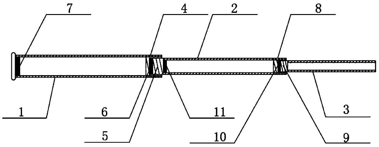
[0025] Such as figure 1 As shown, a telescopic baton includes an outer tube 1, a middle tube 2 and an inner tube 3,

[0026] A middle pipe 2 is movably inserted in the outer pipe 1, and one end of the middle pipe 2 located inside the outer pipe 1 is connected with a first screw rod 5, and the first screw rod 5 is threadedly connected with a first internally threaded sleeve 4, and the first internally threaded sleeve 4 is connected through the outer tube 1, the end of the first screw 5 away from the middle tube 2 is connected with the first magnet 6, and the inner wall of the outer tube 1 is connected with the second magnet 7,

[0027] The middle pipe 2 is movably inserted with an inner pipe 3, and one end of the inner pipe 3 located inside the middle pipe 2 is connected with a second screw 9, and the second screw 9 is threadedly connected with a second internally threaded sleeve 8, and the second internally threaded sleeve 8 is connected through the middle tube 2, the end of ...

Embodiment 2

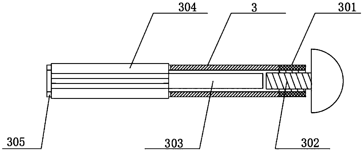
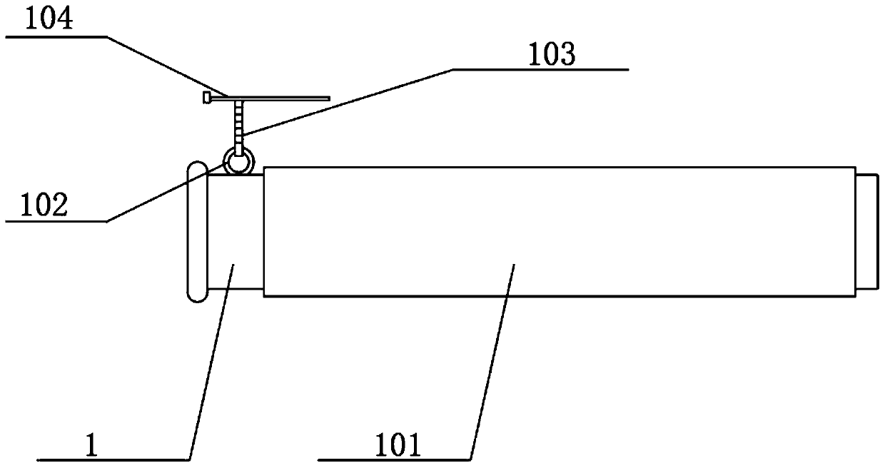
[0031] Such as Figure 1-3 As shown, a telescopic baton includes an outer tube 1, a middle tube 2 and an inner tube 3,

[0032] A middle pipe 2 is movably inserted in the outer pipe 1, and one end of the middle pipe 2 located inside the outer pipe 1 is connected with a first screw rod 5, and the first screw rod 5 is threadedly connected with a first internally threaded sleeve 4, and the first internally threaded sleeve 4 is connected through the outer tube 1, the end of the first screw 5 away from the middle tube 2 is connected with the first magnet 6, and the inner wall of the outer tube 1 is connected with the second magnet 7,

[0033] The middle pipe 2 is movably inserted with an inner pipe 3, and one end of the inner pipe 3 located inside the middle pipe 2 is connected with a second screw 9, and the second screw 9 is threadedly connected with a second internally threaded sleeve 8, and the second internally threaded sleeve 8 is connected through the middle tube 2, the end ...


PUM


Abstract

The invention relates to the technical field of telescopic batons, in particular to a telescopic baton which comprises an outer pipe, a middle pipe and an inner pipe. The middle pipe is movably inserted into the outer pipe, a first screw rod is connected to the end, located inside the outer pipe, of the middle pipe, a first inner threaded sleeve is in threaded connection with the first screw rod,the first inner threaded sleeve is in through connection with the outer pipe, a first magnet is connected to the end, far away from the middle pipe, of the first screw rod, and a second magnet is connected to the inner side wall of the outer pipe. The inner pipe is pulled out, a second screw rod is connected with a second inner threaded sleeve, the middle pipe is pulled out, the first screw rod isconnected with the first inner threaded sleeve, the relative positions of the outer pipe, the middle pipe and the inner pipe are fixed, the fixing mode is simple and convenient, springback is not caused after in-place fixing is realized, and normal use of the baton is ensured. When the telescopic baton is in use, the middle pipe and the inner pipe are pulled out, when the telescopic baton is notin use, the middle pipe and the inner pipe are retracted into the outer pipe, and operation is easy and convenient.

Description

technical field [0001] The invention relates to the technical field of batons, in particular to a retractable baton. Background technique [0002] Baton is a must-have police weapon for front-line public security officers in China. It has a wide range of functions, strong aggressiveness, easy to carry, and tight defense. Various baton defense techniques were practiced. [0003] The telescopic baton is a kind of baton. During the use of the telescopic baton, the thrown part is easy to cause rebound, which affects the use of public security officers. When fighting with suspects, it may even cause arrest failure. [0004] For the problems referred to above, a kind of retractable baton is designed. Contents of the invention [0005] The object of the present invention is to provide a telescopic baton to solve the above technical problems. [0006] In order to solve the problems of the technologies described above, the present invention adopts the following technical solutio...

Claims


Application Information

Patent Timeline
IPC IPC(8): F41B15/02
CPCF41B15/022
Inventor 刘彬
Owner 安徽蓝剑警用装备制造有限公司
Learn More