Manifold device for fuel cell stack

A fuel cell stack and manifold technology, which is applied to fuel cells, fuel cell additives, circuits, etc., can solve the problems of inconvenient mass production, low performance of battery cells, and insufficient effect to meet the uniformity of gas distribution. The effect of increasing volume power density and improving overall performance

Active Publication Date: 2020-06-05
WUHAN UNIV OF TECH
View PDF4 Cites 6 Cited by
  • Summary
  • Abstract
  • Description
  • Claims
  • Application Information

AI Technical Summary

Problems solved by technology

The fuel cell manifold is affected by factors such as flow resistance and throttling. It is difficult to ensure uniform intake pressure and intake volume of each battery unit in the stack. The resulting problem is that there are differences in performance between battery units, and further The performance of the battery unit with insufficient gas volume is low, and the battery unit with too much gas volume causes waste of gas due to excess gas, resulting in a decrease in the output power of the stack
[0004] At present, in the existing fuel cell stack manifold, the flow uniformity of the reactant gas flowing through each unit cell in the stack is not ideal, and the gas flow rate of the battery cells at both ends is quite different.
Using a tapered manifold, although the uniformity of the gas is slightly improved, the effect is not enough to meet the purpose of greatly improving the uniformity of gas distribution. In addition, there are differences in the size of the bipolar plates, which is not convenient for mass production

Method used


Image

  • Manifold device for fuel cell stack
  • Manifold device for fuel cell stack

Examples


Embodiment 1

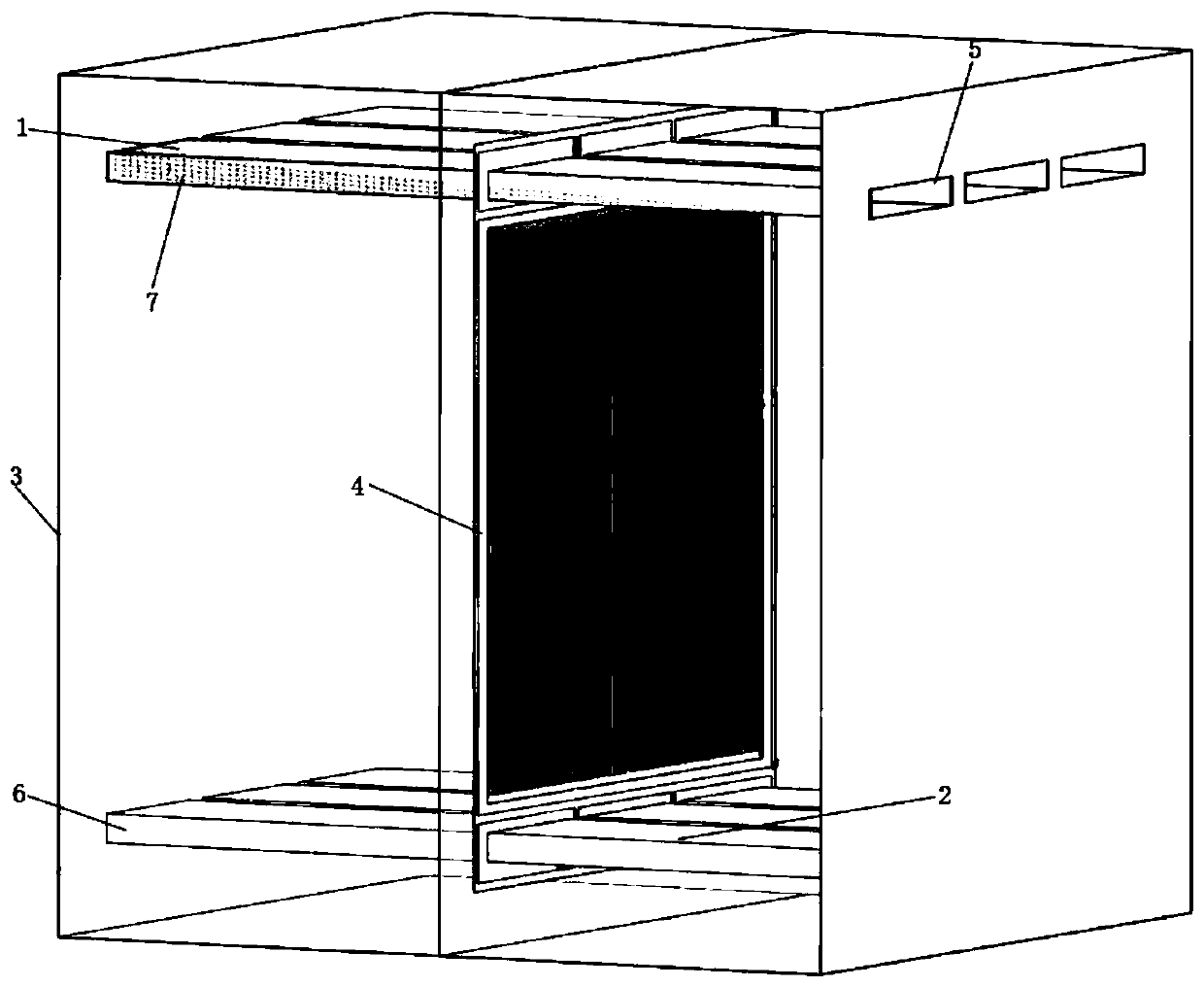
[0022] The blocking block is made of porous material and fills the entire inner cavity of the intake manifold, and the porosity of the blocking block decreases along the air intake direction.

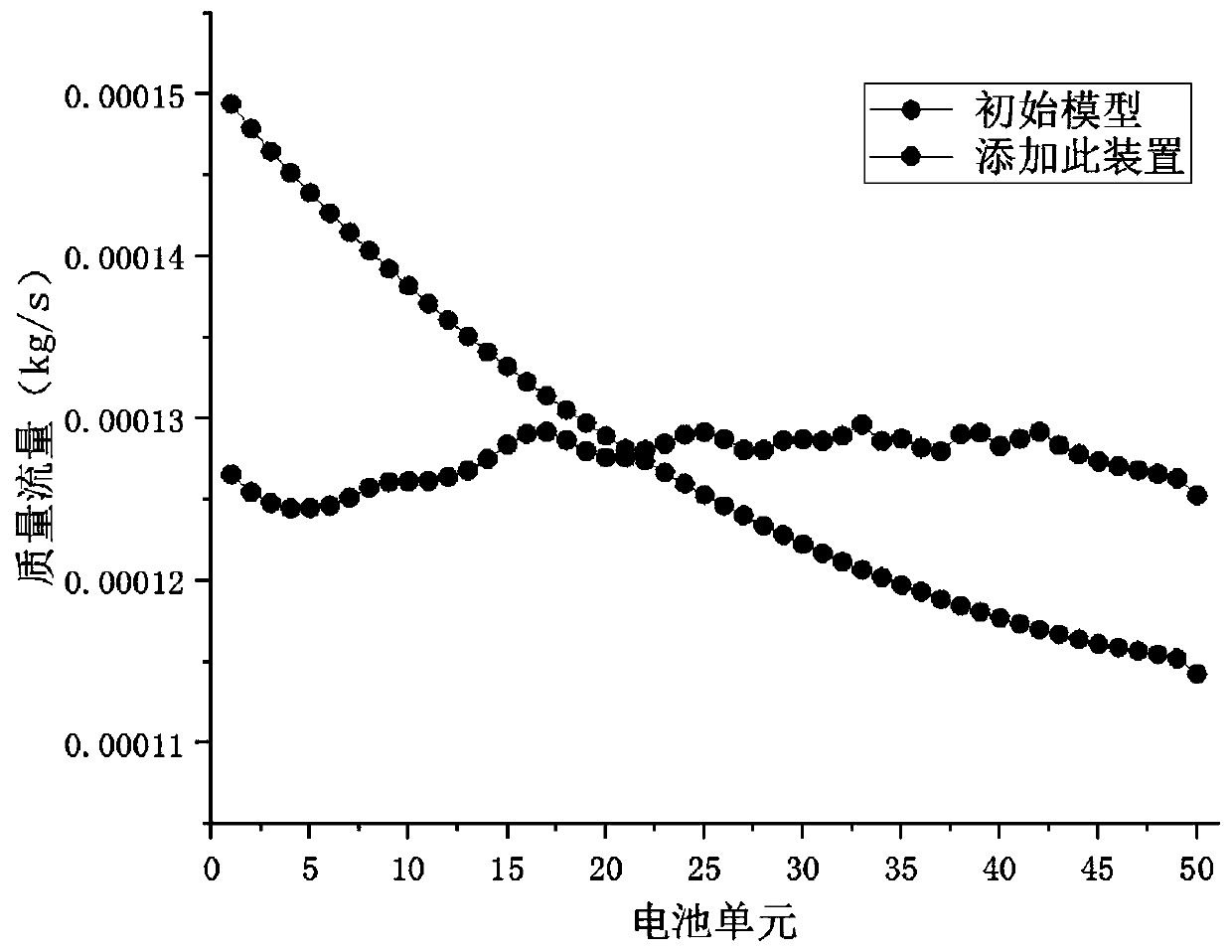
[0023] The fuel gas enters the stack from the inlet of the intake manifold. When the gas flows through the block, the porosity is adjusted to make the gas flow through the battery cells near the inlet different from the gas flow of the battery cells far from the inlet. The change of the gas distribution improves the gas distribution performance of the rectangular duct inlet pipe with poor uniformity of gas flow distribution, improves the flow uniformity, and improves the performance and service life of the overall battery stack.

Embodiment 2

[0025] The blocking block is made of porous material, the thickness of the blocking block increases along the air intake direction, and the porosity is uniform.

[0026] Using 3D printing technology, it is possible to realize the trapezoidal or triangular structure of the porous material block forming with gradual thickness, increase the thickness of the porous material at the position where the air volume of the intake manifold is large, and reduce the porous material at the position where the air volume of the intake manifold is small The thickness of the material.

[0027] The porosity of the block is uniform, and the gas distribution performance of the intake manifold can be improved by adjusting the thickness of the block.

Embodiment 3

[0029] The blocking block is composed of multiple sub-blocks arranged at even intervals along the air intake direction, and the height of the blocking block increases along the air intake direction.

[0030] The sub-block is composed of front and rear fixing plates and cylindrical blocks. Several pairs of locking protrusions are symmetrically arranged on the inner surfaces of the front and rear fixing plates, and the cylindrical blocks are arranged horizontally. , the size of the front and rear fixed blocks is configured with the inner cavity of the intake manifold, and is installed in cooperation with the clearance of the intake manifold, and the number of cylindrical blocks on the multiple sub-blocks increases along the intake direction. The thickness of the front and rear fixing plates is as small as possible, and they are integrated with the cylindrical block and then embedded in the inner cavity of the intake manifold. The installation is stable and the position will not b...


PUM


Abstract

The invention provides a manifold device for a fuel cell stack. The manifold device comprises an intake manifold and an exhaust manifold which are symmetrically arranged up and down, the inlet of theintake manifold and the outlet of the exhaust manifold are respectively positioned at the left and right sides of the fuel cell stack, and a plurality of air inlets are uniformly formed at the bottomof the air inlet manifold at intervals and correspond to the gas inlets of the unit cells in the fuel cell stack respectively. A plurality of exhaust ports are uniformly formed at the top of the exhaust manifold at intervals and correspond to the exhaust ports of the unit cells in the fuel cell stack respectively, and a gas homogenizing device is arranged in the gas inlet manifold and is used foradjusting the gas inlet uniformity of the unit cells, so that the uniformity of flow distribution of reaction gas entering the unit cells can be effectively improved.

Description

technical field [0001] The invention belongs to the technical field of fuel cell stacks, in particular to a manifold device for fuel cell stacks. Background technique [0002] A fuel cell is a power generation device that directly converts chemical energy in fuel into electrical energy. It can be used as a The main power source of various transportation vehicles. In order to meet the power requirements, a certain number of unit cells are usually assembled in series to form a stack to ensure sufficient output power. [0003] The fuel cell inlet and outlet gas manifolds are respectively responsible for distributing the externally supplied fluid to each unit cell for reaction, and collecting and discharging the remaining gas from the stack. The fuel cell manifold is affected by factors such as flow resistance and throttling. It is difficult to ensure uniform intake pressure and intake volume of each battery unit in the stack. The resulting problem is that there are difference...

Claims


Application Information

Patent Timeline
Patent Type & Authority Applications(China)
IPC IPC(8): H01M8/2483H01M8/0265H01M8/04082H01M8/04089H01M8/04746H01M8/04828
CPCH01M8/0265H01M8/04089H01M8/04201H01M8/04753H01M8/04783H01M8/0494H01M8/2483Y02E60/50
Inventor 陈奔刘英杰孟凯刘阳柳琪
Owner WUHAN UNIV OF TECH
Why Eureka
Try Eureka