Liquid cooling heat dissipation direct current charging device

A DC charging, liquid-cooled heat dissipation technology, applied in charging stations, electric vehicle charging technology, electric vehicles, etc., can solve the problems of increasing product volume and weight, small fan frontal area, and large thickness of heat dissipation fins, etc., to improve volume Power density, improved heat dissipation efficiency, and short heat transfer path

Pending Publication Date: 2022-01-07
美达电器(重庆)有限公司
View PDF0 Cites 1 Cited by
  • Summary
  • Abstract
  • Description
  • Claims
  • Application Information

AI Technical Summary

Problems solved by technology

Charging piles using this heat dissipation method generally have the characteristics of large volume and weight, poor heat dissipation effect, and high working noise.
This kind of charging product has the following disadvantages: first, the thickness of the heat dissipation fins is large, the heat dissipation area per unit volume is small, and the heat dissipation efficiency is low; the second is to obtain a larger heat dissipation area, which will lead to a substantial increase in the volume and weight of the product. ; The third is that the windward area of ​​the fan is small, and the number of fans is large, which will lead to high working noise; the fourth is that the use of more heat-conducting links and larger shell parts will lead to difficult production and high manufacturing costs
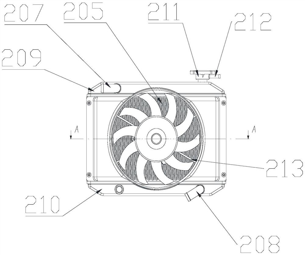
[0004] The tube belt air coolers commonly used in the market today generally use a single row of heat dissipation pipes, which has a small heat dissipation area and low overall heat dissipation efficiency.

Method used


Image

  • Liquid cooling heat dissipation direct current charging device
  • Liquid cooling heat dissipation direct current charging device
  • Liquid cooling heat dissipation direct current charging device

Examples


Embodiment Construction

[0034] The preferred embodiments of the present invention will be described in detail below in conjunction with the accompanying drawings, so that the advantages and features of the present invention can be more easily understood by those skilled in the art, so as to define the protection scope of the present invention more clearly.

[0035] It should be noted that, in the description of the present invention, the terms "center", "upper", "lower", "left", "right", "vertical", "horizontal", "inner", "outer" etc. The terms of the indicated direction or positional relationship are based on the direction or positional relationship shown in the drawings, and these terms are only for convenience of description, and do not indicate or imply that the device or element must have a specific orientation, or a specific orientation configuration and operation and therefore should not be construed as a limitation of the invention. In addition, the terms "first", "second", and "third" are us...


PUM


Abstract

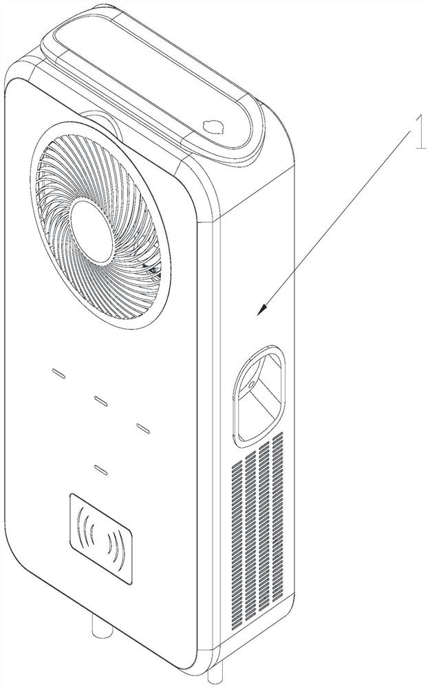
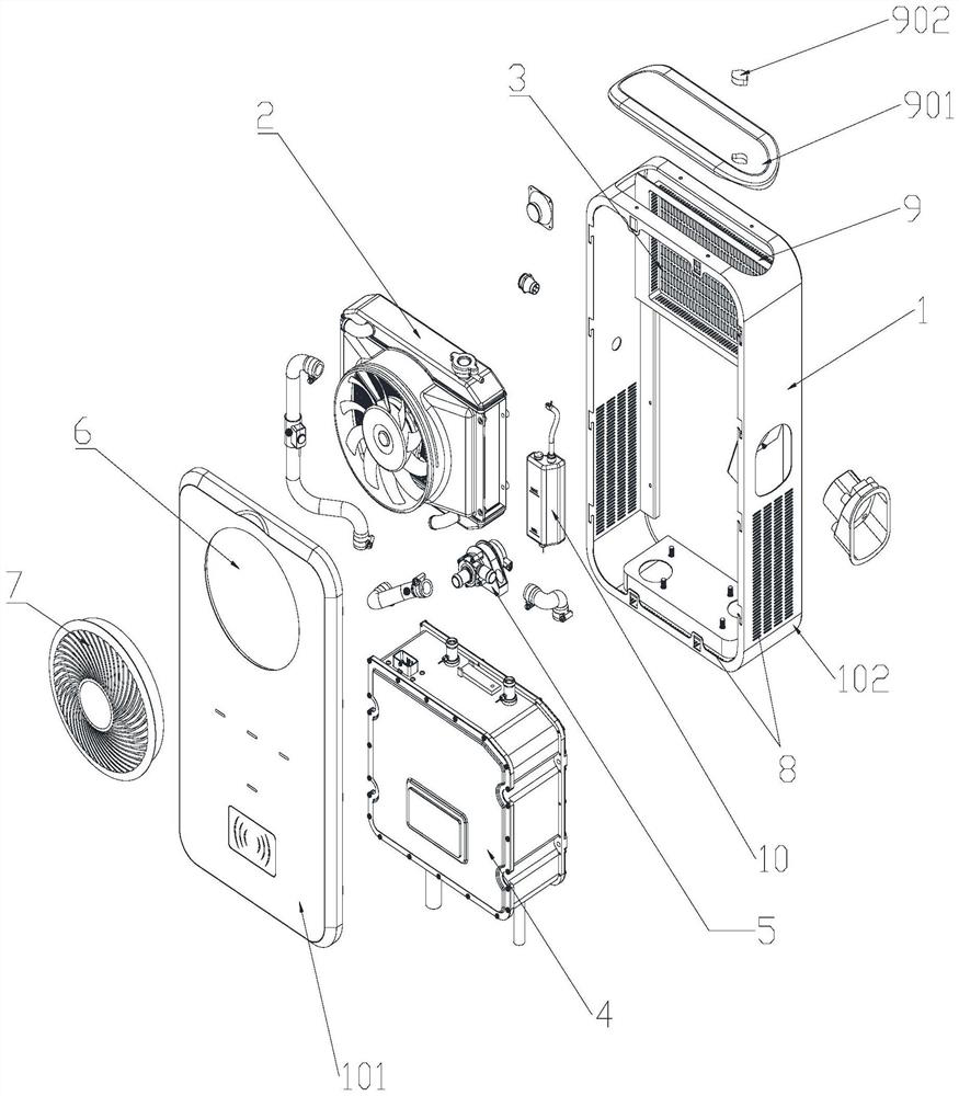
The invention provides a liquid cooling heat dissipation direct current charging device which comprises a shell (1), an air cooling mechanism (2) is installed on the upper portion of the inner cavity of the shell (1), at least one first air inlet (3) is formed in the surface of the shell (1), and the first air inlet (3) and the air cooling mechanism (2) are arranged correspondingly; a liquid cooling charging module (4) is arranged at the lower part of the inner cavity of the shell (1); a water inlet and a water outlet of the liquid cooling charging module (4) are respectively communicated with a water outlet and a water inlet of the air cooling mechanism (2); a water pump mechanism (5) is connected in series between the water inlet of the liquid cooling charging module (4) and the water outlet of the air cooling mechanism (2) or between the water outlet of the liquid cooling charging module (4) and the water inlet of the air cooling mechanism (2).

Description

technical field [0001] The invention relates to the technical field of charging devices for electric vehicles, in particular to a liquid-cooled and heat-dissipating DC charging device. Background technique [0002] With the vigorous promotion and application of electric vehicle technology, the output of electric vehicles is increasing day by day, and electric vehicles have entered thousands of households. At the same time, the output of electric vehicles has grown exponentially, and the demand for charging piles is also huge. Although the number of charging piles is also increasing rapidly, the growth scale of the number of new energy vehicles is much higher than the growth scale of the number of charging piles. The rapid expansion of the production scale of the electric vehicle industry has promoted the rapid development of the charging pile industry. On the contrary, the lag in the development of the charging pile industry will seriously affect the expansion of the produ...

Claims


Application Information

Patent Timeline
Patent Type & Authority Applications(China)
IPC IPC(8): B60L53/302B60L53/31
CPCB60L53/302B60L53/31Y02T10/70Y02T10/7072Y02T90/12
Inventor 袁大东陈杰孟令杰
Owner 美达电器(重庆)有限公司
Why Eureka
Try Eureka