
Capacitance tomography sensor

A technology of capacitance tomography and sensors, which is applied in the field of sensors, can solve the problems of stray capacitance of shielding layers and shielding cover placement methods, difficulty in measuring electrode layout and installation, and reducing the quality of reconstructed images, so as to improve quality and stability, Effects of reducing interference from measurement noise and increasing sensitivity

Active Publication Date: 2015-05-27
INST OF ENGINEERING THERMOPHYSICS - CHINESE ACAD OF SCI
View PDF9 Cites 27 Cited by
  • Summary
  • Abstract
  • Description
  • Claims
  • Application Information

AI Technical Summary

Problems solved by technology

[0005] However, for large-scale polygonal measurement objects, there are two insurmountable disadvantages in the existing electrical capacitance tomography sensor design: First, with the irregular cross-sectional shape of the measured area and the increase in scale, the arrangement of measurement electrodes and Installation becomes more difficult; secondly, the existing shielding layer and the placement of the shielding cover will introduce non-negligible stray capacitance, which will affect the measurement results
In addition, as the scale of the measured area increases, the sensitivity of the central region of the electrical capacitance tomography sensor will decrease significantly, and the conventional single-electrode excitation-single-electrode measurement excitation measurement mode will reduce the quality of the reconstructed image

Method used


Image

  • Capacitance tomography sensor
  • Capacitance tomography sensor
  • Capacitance tomography sensor

Examples


Embodiment Construction

[0025] In order to make the object, technical solution and advantages of the present invention clearer, the present invention will be described in further detail below in conjunction with specific embodiments and with reference to the accompanying drawings. It should be noted that, in the drawings or descriptions of the specification, similar or identical parts all use the same figure numbers. Implementations not shown or described in the accompanying drawings are forms known to those of ordinary skill in the art. Additionally, while illustrations of parameters including particular values ​​may be provided herein, it should be understood that the parameters need not be exactly equal to the corresponding values, but rather may approximate the corresponding values ​​within acceptable error margins or design constraints. The directional terms mentioned in the embodiments, such as "upper", "lower", "front", "rear", "left", "right", etc., are only referring to the directions of the...


PUM


Abstract

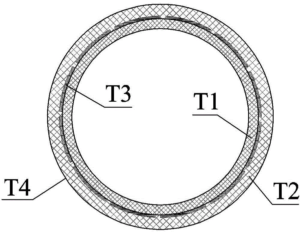
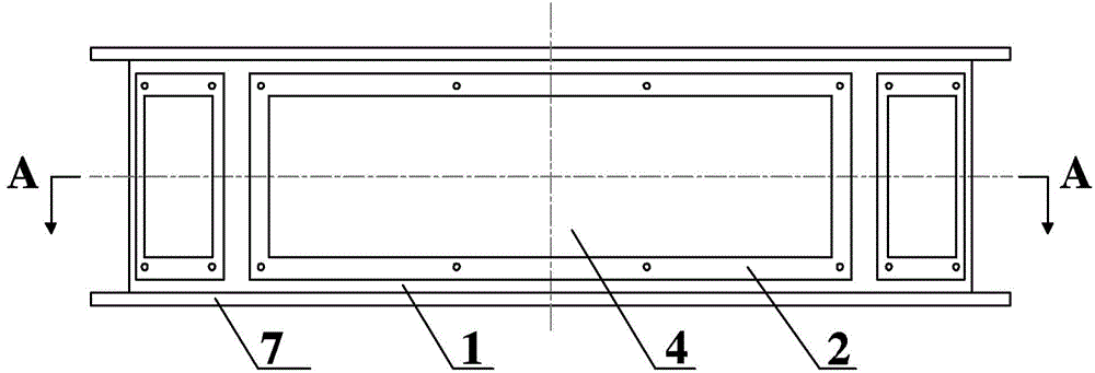
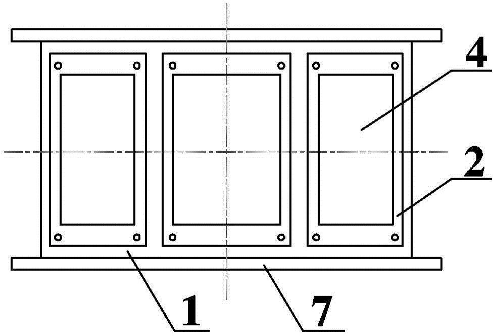
A capacitance tomography sensor is provided in the invention, wherein a sensor framework is added to the capacitance tomography sensor. A measurement electrode is arranged on an inner wall of the sensor framework to prevent direct contact between the measurement electrode and a to-be-test fluid. A shield electrode group is disposed on an outer side surface of the sensor framework to achieve electrical insulation from the measurement electrodes. By means of the structure, installation of the measurement electrode and the shield electrode group is more flexible.

Description

technical field [0001] The invention relates to the technical field of sensors, in particular to a capacitance tomography sensor. Background technique [0002] With the improvement of the parameters and capacity of the circulating fluidized bed boiler, the particle flow law inside it becomes extremely complex, and the uniformity of air distribution in the dense phase area is particularly important. However, the lack of real-time and effective cross-sectional particle concentration distribution measurement technology hinders the description of the internal fluid dynamics of circulating fluidized bed boilers. Generally speaking, the dynamic characteristics of the fluid inside the circulating fluidized bed can usually be obtained by using intrusive point measurement techniques, such as momentum probes, capacitance probes and fiber optic probes. However, these methods can only measure local and transient particle concentrations. As the flow scale increases, point measurement me...

Claims


Application Information

Patent Timeline
Patent Type & Authority Applications(China)
IPC IPC(8): G01N27/22
Inventor 叶佳敏王海刚邱桂芝
Owner INST OF ENGINEERING THERMOPHYSICS - CHINESE ACAD OF SCI
Learn More