Step-by-step reaction type metal fuel cell system
A metal fuel cell and fuel cell technology, applied in fuel cells, fuel cell additives, fuel cell half-cells, and secondary battery-type half-cells, can solve problems such as electrolyte drying up and meet energy density requirements And low cost, high energy density and low cost, eliminate the effect of corrosion reaction
Active Publication Date: 2020-06-05
JINGMEN CITY DREAM EXPLORATION TECH CO LTD
View PDF9 Cites 0 Cited by
- Summary
- Abstract
- Description
- Claims
- Application Information
AI Technical Summary
Problems solved by technology
[0010] The present invention aims at the deficiencies of the above-mentioned prior art, and provides a step-by-step reaction metal fuel cell system. By adopting a step-by-step reaction method, the metal-air battery reaction is divided into two steps, and the metal anode reaction part is in a clo
Method used
View moreImage
Smart ImageViewing Examples

Examples
 PUM
 Abstract
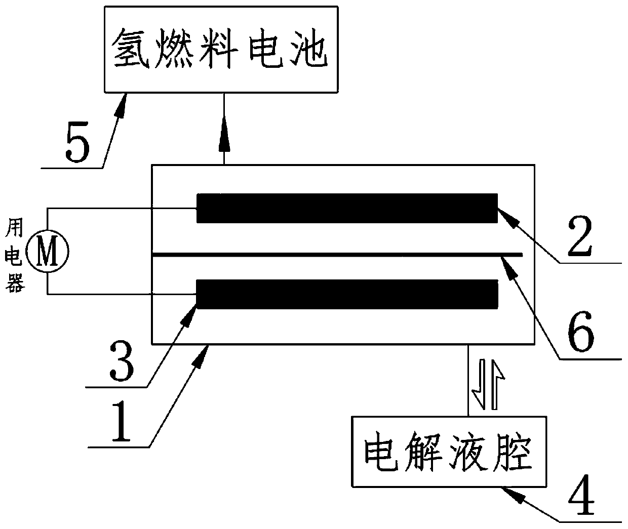
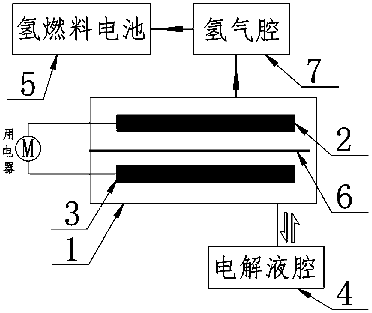
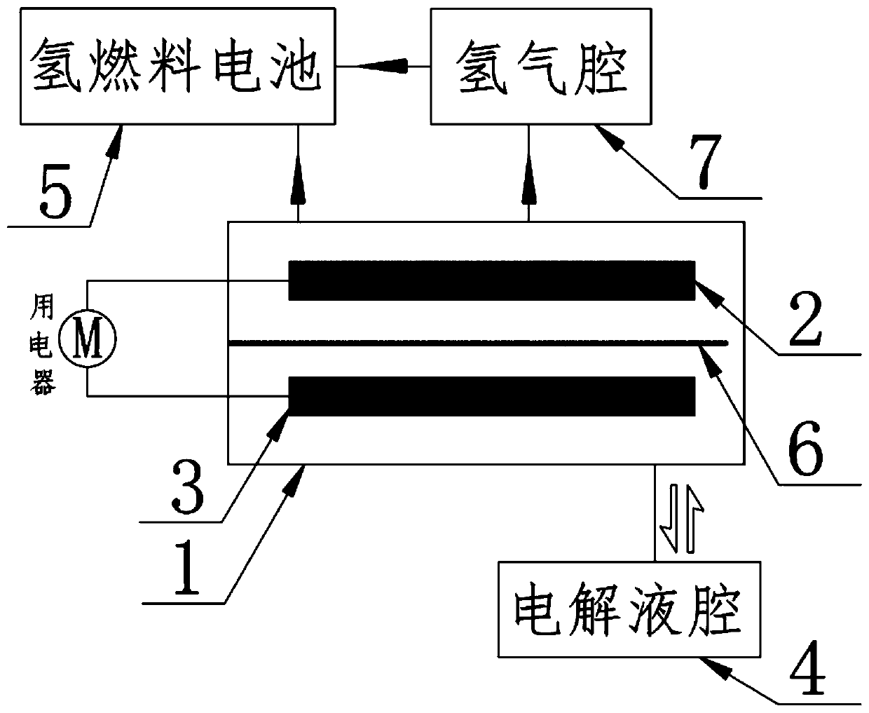
The invention relates to the field of new energy, and discloses a step-by-step reaction type metal fuel cell system. The system comprises a reaction cavity, a water electrode, a metal electrode, an electrolyte cavity and a hydrogen fuel cell; the water electrode and the metal electrode are respectively positioned in the reaction cavity and are respectively led out of the reaction cavity through leads; the reaction cavity is connected with the electrolyte cavity through a pipeline; and an electrolyte is contained in the electrolyte cavity. A hydrogen source is provided for the hydrogen fuel cell through reaction in the reaction cavity, a step-by-step reaction mode is adopted, the reaction of the metal-air battery is divided into two steps, the metal anode reaction part is in a closed environment, the problems of electrolyte drying and alkali leakage are solved, and then the valve between the reaction cavity and the hydrogen cavity is closed, so that the hydrogen generated in the reaction cavity can be gathered in the reaction cavity, the pressure in the reaction cavity is increased, the electrolyte is pressed back into the electrolyte cavity, the metal anode is separated from the electrolyte and is positioned in a reduction protection atmosphere of the hydrogen, and the occurrence of corrosion reaction can be completely avoided.
Description
technical field [0001] The invention relates to the field of new energy, in particular to a step-by-step reaction type metal fuel cell system. Background technique [0002] In order to solve the environmental problems and energy crisis caused by traditional fossil fuels, countries are currently vigorously developing new energy technologies, and many European countries have given a ban on the sale of fuel vehicles. [0003] Among many new energy technologies, lithium battery technology is currently the fastest-growing new energy technology. However, due to the constraints of the chemical system of the lithium battery itself, its disadvantages are very obvious, and it cannot compete with the fuel energy system in many cases. First of all, the charging time of lithium batteries usually takes tens of minutes to several hours, which greatly reduces the convenience; second, the theoretical energy density of lithium batteries is only 240Wh / Kg~350Wh / Kg, which is far lower than the ...
Claims
Login to View More Application Information
Patent Timeline
 IPC IPC(8): H01M12/08H01M10/28H01M10/38H01M8/04082H01M8/04089
CPCH01M8/04089H01M8/04201H01M10/288H01M10/38H01M12/08Y02E60/10Y02E60/50Y02P70/50
Inventor 王广军余为伟
Owner JINGMEN CITY DREAM EXPLORATION TECH CO LTD
Features
- R&D
- Intellectual Property
- Life Sciences
- Materials
- Tech Scout
- Unparalleled Data Quality
- Higher Quality Content
- 60% Fewer Hallucinations
Learn More Browse by: Latest US Patents, China's latest patents, Technical Efficacy Thesaurus, Application Domain, Technology Topic, Popular Technical Reports.
© 2025 PatSnap. All rights reserved.Legal|Privacy policy|Modern Slavery Act Transparency Statement|Sitemap|About US| Contact US: help@patsnap.com