A rotary throwing integrated washing machine

A cleaning machine and integrated technology, applied in the directions of cleaning methods using liquids, cleaning methods and utensils, chemical instruments and methods, etc., can solve the problem of large energy consumption of cleaning machines, and achieve the effect of easy removal

Active Publication Date: 2020-12-08
深圳市和科达超声设备有限公司
View PDF10 Cites 0 Cited by
  • Summary
  • Abstract
  • Description
  • Claims
  • Application Information

AI Technical Summary

Problems solved by technology

However, in the cleaning machine with this structure, since the motor on the cleaning tank and its output transmission mechanism all move up and down with the throwing motion, the energy consumption of the cleaning machine is large during operation.

Method used


Image

  • A rotary throwing integrated washing machine
  • A rotary throwing integrated washing machine
  • A rotary throwing integrated washing machine

Examples


Embodiment Construction

[0035] The present invention will be described in further detail below in conjunction with the accompanying drawings.

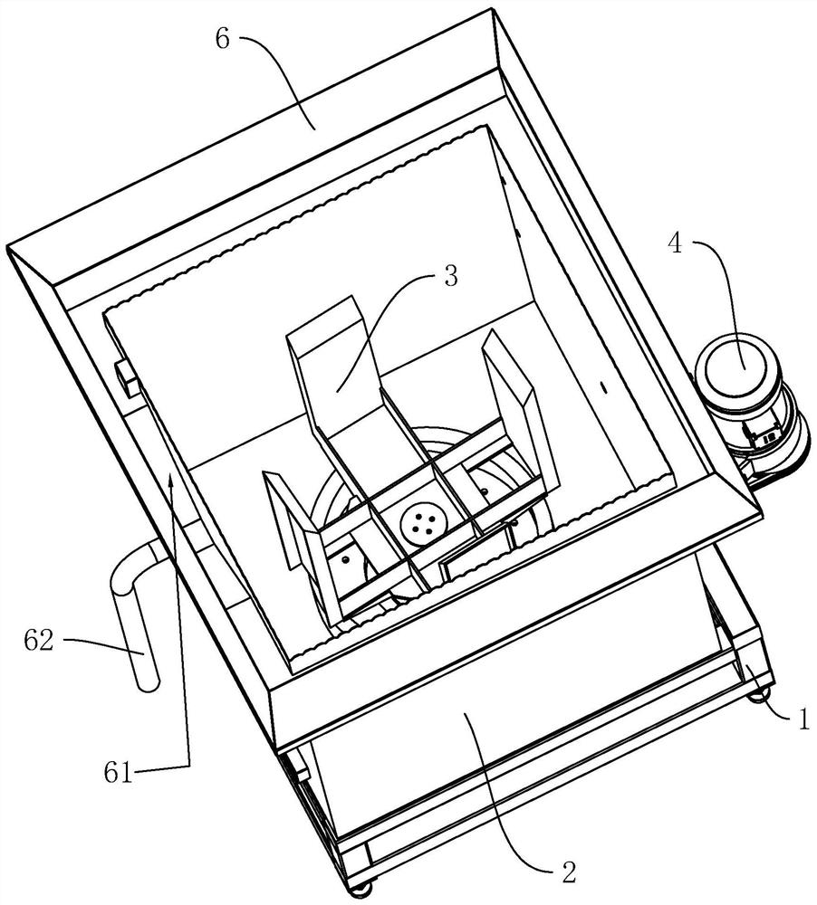
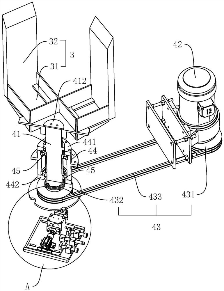
[0036] refer to figure 1 , is a rotary throwing integrated cleaning machine disclosed by the present invention, comprising a base 1 and a cleaning tank 2 fixedly arranged on the base 1, the cleaning tank 2 is provided with a rotating bracket 3 for installing a cleaning basket, and the rotating bracket 3 includes The cross-shaped rotating seat 31 and four supporting plates 32 vertically arranged at the ends of the rotating seat 31, the cleaning basket is vertically placed on the inside of the four supporting plates 32, and the outer wall of the cleaning basket is in conflict with the inner wall of the supporting plate 32, thereby ensuring During the operation of the cleaning machine, the cleaning basket and the rotating bracket 3 are kept stable and run synchronously.

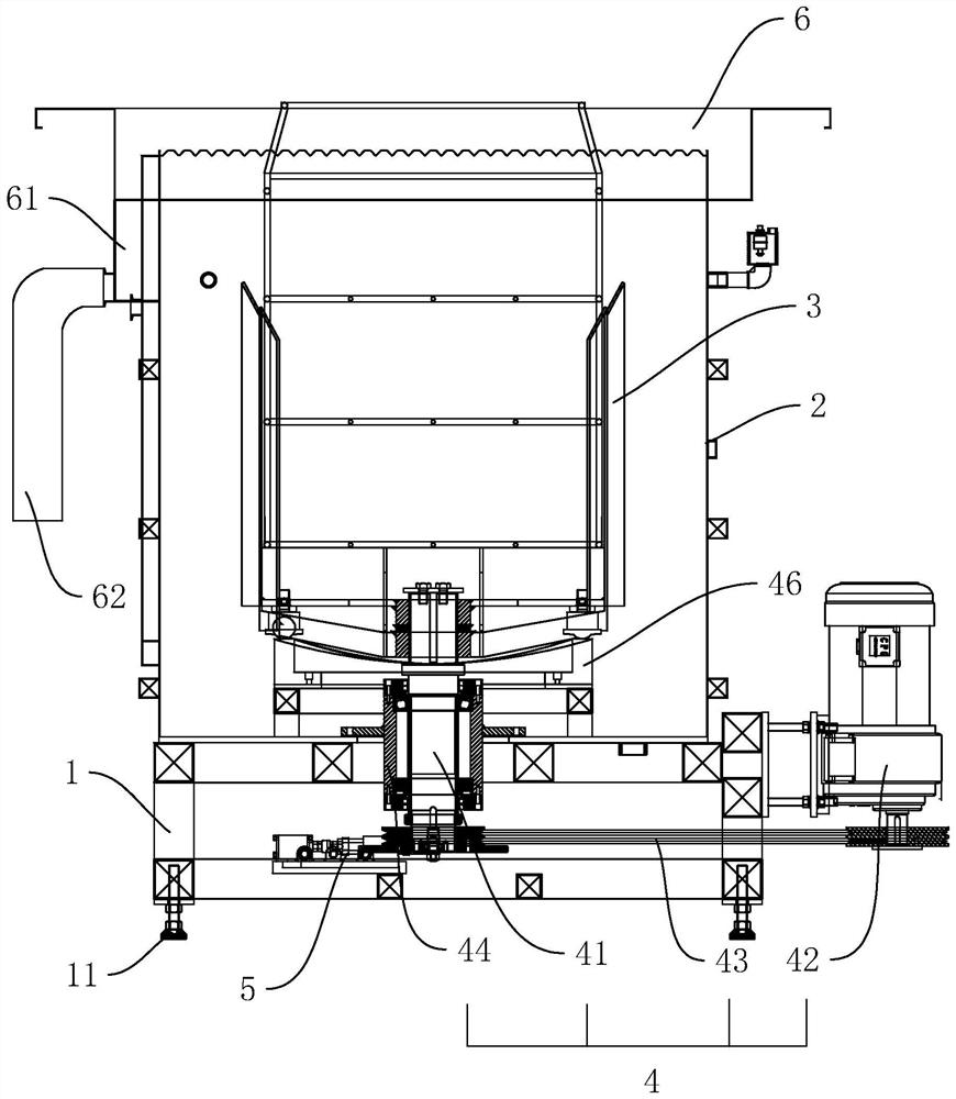
[0037] refer to figure 1 and figure 2The outer side of the top of the cleaning tank 2 i...


PUM


Abstract

The invention relates to a rotating and throwing integration cleaning machine, and belongs to the field of ultrasonic cleaning equipment. The rotating and throwing integration cleaning machine comprises a base and a cleaning tank fixedly arranged on the base, wherein a rotating bracket for installing a cleaning basket is arranged in the cleaning tank and is connected with a rotating and throwing device; the rotating and throwing device comprises a driving shaft vertically arranged at the lower end of the rotating bracket, and a brake motor fixedly arranged on the base; a transmission mechanismis arranged between the brake motor and the driving shaft, so that the driving shaft drives the rotating bracket to rotate; a cylindrical cam with a curved-surface-shaped upper end face is fixedly arranged on the bottom wall in the cleaning tank; the driving shaft penetrates through the cylindrical cam; two support pieces abutted against the upper end face of the cylindrical cam are symmetricallyarranged at the lower end of the rotating bracket; and the rotating bracket and the driving shaft are arranged up and down in a sliding way. According to the rotating and throwing integration cleaning machine provided by the invention, through arranging the rotating and throwing device, the cleaning basket can realize throwing and rotating movement at the same time under the drive of the brake motor, so that the energy consumption caused by the operation of the cleaning machine is reduced.

Description

technical field [0001] The invention relates to the field of ultrasonic cleaning equipment, in particular to a rotary throwing integrated cleaning machine. Background technique [0002] The ultrasonic cleaning machine uses the cavitation reaction of ultrasonic waves in the cleaning liquid, plus the throwing and cleaning device to accelerate the dissolution and stripping of the cleaned workpieces, surface workpieces of components, dust, grease, etc. in inner hole components and blind holes. The cleaning speed is fast, the effect is good, the parts are not damaged and the labor intensity is reduced. [0003] But existing cleaning machines usually need two power sources to control the rotation and throwing of the cleaning basket respectively, wherein a motor is usually used as the power for the rotation of the cleaning basket, and a cylinder is arranged below the motor as the throwing power of the cleaning basket. Drive the motor and the transmission mechanism of the motor to ...

Claims


Application Information

Patent Timeline
Patent Type & Authority Patents(China)
IPC IPC(8): B08B3/12B08B3/10B08B3/04B08B13/00
CPCB08B3/045B08B3/10B08B3/123B08B13/00
Inventor 卢争驰周柏雄
Owner 深圳市和科达超声设备有限公司
Why Eureka
Try Eureka