An easy-to-use rust removal device for metal surfaces

A metal surface and support plate technology, which is applied in the direction of grinding drive devices, metal processing equipment, grinding machine parts, etc., can solve the problems of affecting the user's production efficiency, poor derusting effect of tubular metal, and time-consuming, etc., to achieve Good rust removal function, simple structure, and the effect of improving production efficiency

Active Publication Date: 2021-09-21
哈尔滨双通铸锻有限责任公司
View PDF4 Cites 0 Cited by
  • Summary
  • Abstract
  • Description
  • Claims
  • Application Information

AI Technical Summary

Problems solved by technology

[0004] However, due to the relatively simple structure of the derusting device, the derusting effect of the derusting device on the tubular metal is poor, so that the user needs to spend a lot of time when derusting the tubular metal, which affects the user's production efficiency

Method used


Image

  • An easy-to-use rust removal device for metal surfaces
  • An easy-to-use rust removal device for metal surfaces
  • An easy-to-use rust removal device for metal surfaces

Examples


Embodiment 1

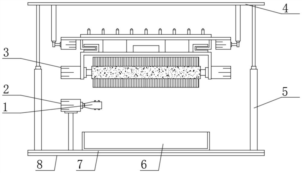
[0023] see Figure 1-Figure 3 , the present invention provides a technical solution: an easy-to-use metal surface derusting device, comprising a second support plate 7, one end of the upper surface of the second support plate 7 is fixed with a first drive motor 2 by bolts, the first drive motor The output end of 2 is provided with fixing device 1, and the use of first driving motor 2 and fixing device 1 is prior art, and the top of second supporting plate 7 is provided with first supporting plate 4, and the upper surface of second supporting plate 7 The first electric telescopic rod 5 corresponding to the first support plate 4 is welded at both ends, and a derusting mechanism 3 is arranged under the first support plate 4;

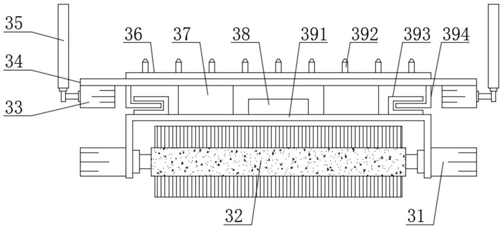
[0024] Derusting mechanism 3 comprises the 3rd support plate 34, the 3rd drive motor 33 is arranged on the lower surface two ends of the 3rd support plate 34, the output end of the 3rd drive motor 33 is provided with the second drive motor 33 corresponding ...

Embodiment 2

[0033] On the basis of Embodiment 1, in order to enrich the function of the derusting device, in this embodiment, preferably, the upper surface of the second support plate 7 is provided with a collection box 6, and the material of the collection box 6 is plastic. The used derusting solution is collected and stored through the collection box 6 to prevent the derusting device from flowing out a large amount of derusting solution during use;

[0034] In order to make the anti-slip effect of the derusting device better, in the present embodiment, preferably, the lower surface of the second support plate 7 is provided with an anti-slip backing plate 8, the anti-slip backing plate 8 is a cuboid structure, and the anti-slip backing plate 8 and the second support Board 7 is connected by glue bonding;

[0035] The material of anti-slip backing plate 8 is not limited, and in the present embodiment, preferred, the material of anti-slip backing plate 8 is rubber, plays anti-slip effect by...


PUM


Abstract

The invention discloses an easy-to-use metal surface derusting device, belonging to the technical field of metal surface treatment, comprising a second support plate, one end of the upper surface of the second support plate is provided with a first drive motor, and an output end of the first drive motor A fixing device is provided, a first support plate is provided above the second support plate, and first electric telescopic rods corresponding to the first support plate are provided at both ends of the upper surface of the second support plate. A derusting mechanism is provided below, and the derusting mechanism includes a third support plate, a third drive motor is provided at both ends of the lower surface of the third support plate, and a first drive motor corresponding to the first support plate is provided at the output end of the third drive motor. 2. Electric telescopic rod; the present invention is simple in structure, easy to use, has good derusting function, can quickly derust tubular metal, effectively shortens the time spent by users in derusting tubular metals, and improves user's production efficiency.

Description

technical field [0001] The invention belongs to the technical field of metal surface treatment, and in particular relates to an easy-to-use metal surface derusting device. Background technique [0002] Chinese patent (publication No. CN205465617U) discloses a tubular metal surface derusting device, including a casing, one side of the casing is respectively opened with a first opening and a second opening, the inside of the casing is provided with a motor, and the motor The rotating shaft of the first connecting rod is fixedly connected to the first connecting rod through a coupling, and the end of the first connecting rod away from the motor penetrates the casing and extends to the outside of the casing, and the surface of the first connecting rod extending to the outside of the casing is fixedly connected with the first connecting rod. A pulley, and the surface of the first pulley is in transmission connection with the second pulley fixedly connected to the surface of the s...

Claims


Application Information

Patent Timeline
Patent Type & Authority Patents(China)
IPC IPC(8): B24B27/033B24B41/00B24B41/06B24B47/12B24B47/22C23G3/02
CPCB24B27/033B24B41/00B24B41/067B24B47/12B24B47/22C23G3/023
Inventor 汪香平
Owner 哈尔滨双通铸锻有限责任公司
Why Eureka
Try Eureka