Fixing member and image forming device

A technology for fixing parts and images, which is applied in printing devices, threaded fasteners, and electrical recording processes using charge patterns, etc., can solve the problem that the rocking parts of the conveying unit cannot move freely, and achieve the effect of suppressing plastic deformation.

Active Publication Date: 2021-11-23
KYOCERA DOCUMENT SOLUTIONS INC
View PDF5 Cites 0 Cited by
  • Summary
  • Abstract
  • Description
  • Claims
  • Application Information

AI Technical Summary

Problems solved by technology

Also, when transporting the image forming apparatus, tighten the screws so that the transport unit cannot move freely relative to the swing member.

Method used


Image

  • Fixing member and image forming device
  • Fixing member and image forming device
  • Fixing member and image forming device

Examples


Embodiment Construction

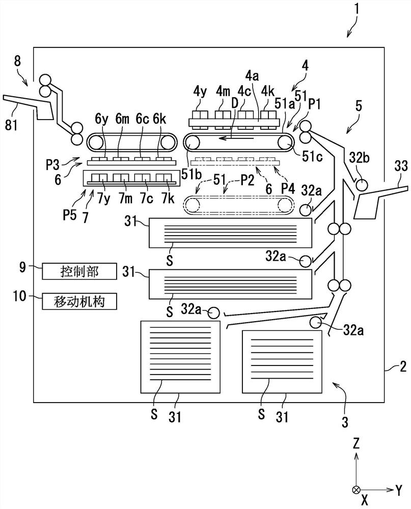
[0020] Hereinafter, the inkjet recording device 1 according to the embodiment of the present invention will be described with reference to the drawings. The inkjet recording device 1 is an example of an image forming device. In addition, the same reference numerals are used for the same or corresponding parts in the drawings, and the description thereof will not be repeated. In addition, in order to facilitate understanding, each constituent element is mainly shown schematically in the drawings.

[0021] refer to figure 1 , the inkjet recording device 1 according to this embodiment will be described. figure 1 This is the inkjet recording device 1 according to this embodiment. The X-axis, Y-axis and Z-axis in the figure are orthogonal to each other. Also, the X axis and the Y axis are parallel to the horizontal direction, and the Z axis is parallel to the vertical direction. The Y-axis direction is a direction opposite to the conveyance direction D. As shown in FIG.

[00...


PUM


Abstract

The invention provides a fixing member and an image forming apparatus. The fixing tool includes a screw member and a ring-shaped spacer member. The screw member includes a base, a protrusion protruding from the base, and a screw portion at the tip of the protrusion. The spacer member is mounted on the protrusion in such a manner as to freely slide between the base and the screw. The first part is clamped by the base and spacer parts. The second part is sandwiched by the nut part and the spacer part, the nut part is screwed on the screw part, and the second part is a different part from the first part.

Description

technical field [0001] The present invention relates to a fixing member and an image forming apparatus. Background technique [0002] An image forming apparatus includes a conveyance unit, a rocker, and a stationary member. The fixings are screws. The fixture mounts the delivery unit freely movable relative to the rocker. Also, when the image forming apparatus is transported, the screws are tightened so that the transport unit cannot move freely relative to the swing member. Contents of the invention [0003] On the other hand, there is generally known an image forming apparatus in which a conveyance unit is supported on a support plate via an elastic body. However, in this image forming apparatus, when the conveying unit (second member) and the support plate (first member) are fixed via the elastic body with screws for fixing, it is difficult to suppress the plastic deformation of the elastic body. . [0004] The present invention has been made in view of the above p...

Claims


Application Information

Patent Timeline
Patent Type & Authority Patents(China)
IPC IPC(8): F16B35/04F16B33/02F16B37/04G03G21/16
CPCF16B35/041F16B33/02F16B37/042G03G21/16G03G21/1647G03G15/6502B41J11/007G03G21/1685
Inventor 山崎俊介
Owner KYOCERA DOCUMENT SOLUTIONS INC
Why Eureka
Try Eureka