Valve with linkage type switches

A linkage type, switch technology, applied in valve details, multi-way valve, valve device and other directions, can solve the problem of unable to achieve cyclic reciprocating liquid supply.

Inactive Publication Date: 2020-06-09
唐学均
View PDF1 Cites 6 Cited by
  • Summary
  • Abstract
  • Description
  • Claims
  • Application Information

AI Technical Summary

Problems solved by technology

However, this valve cannot achieve the effect of reciprocating liquid supply in two directions.

Method used


Image

  • Valve with linkage type switches
  • Valve with linkage type switches
  • Valve with linkage type switches

Examples


specific Embodiment approach 1

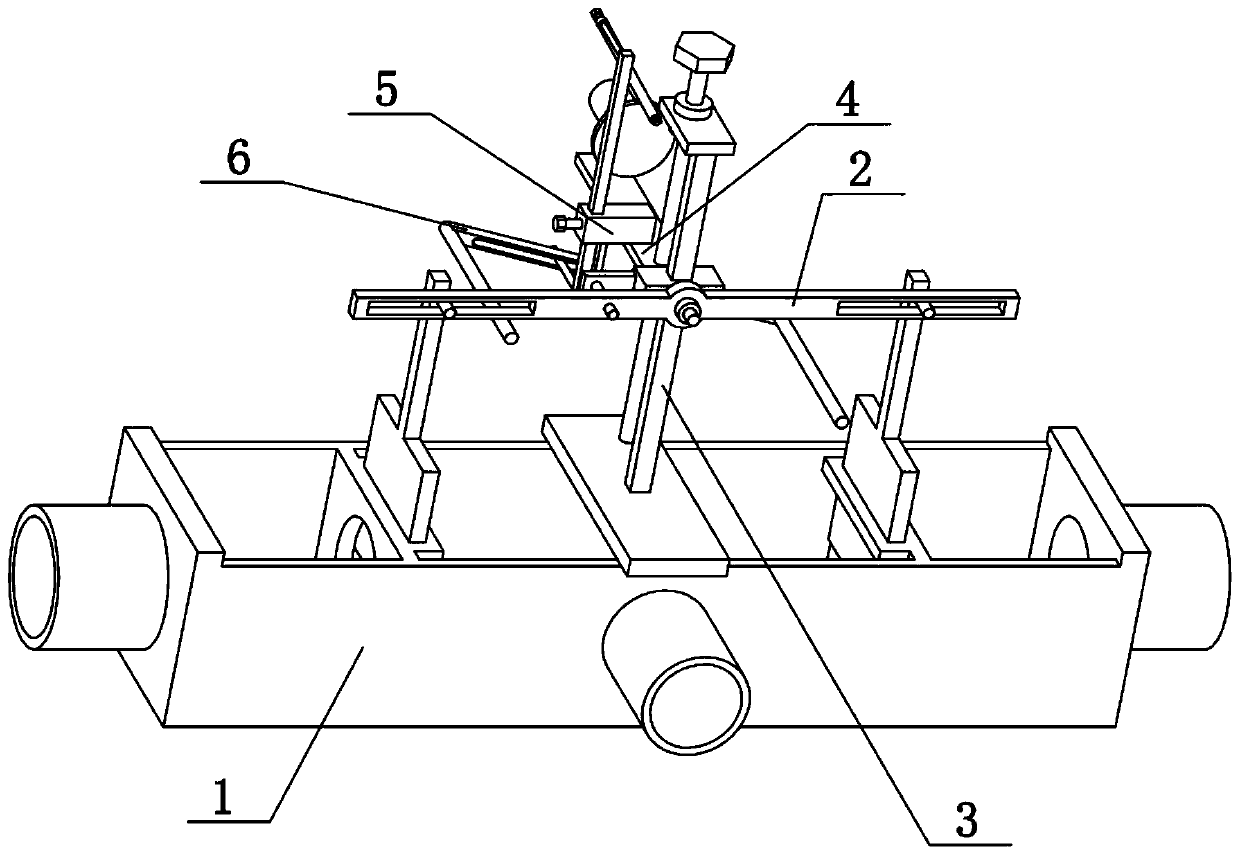
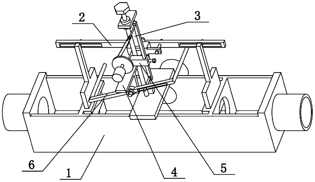
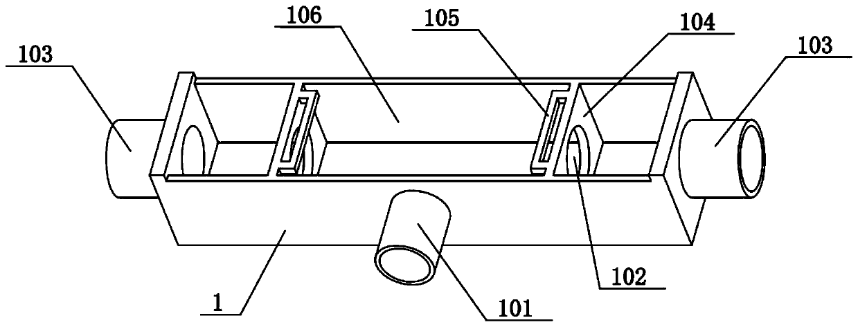
[0028] Combine below Figure 1-7 Description of this embodiment, the present invention relates to a valve, more specifically a valve with a linkage switch, including a square cylinder shell 1, a water inlet 101, a water hole 102, a side water outlet 103, a baffle 104, Rectangular sleeve 105, water storage tank 106, lever 2 and gate 204, the present invention is a three-way valve, the two switches of the present invention can be linked, can be opened and closed at the same time; To achieve the effect of reciprocating liquid supply in two directions.

[0029] The square cylinder shell 1 is a hollow cuboid structure, and the inside of the square cylinder shell 1 is symmetrically provided with two baffles 104, and the two baffles 104 are provided with water holes 102 penetrating left and right, and the two baffles The upper ends of 104 are fixedly connected with rectangular sleeves 105, a water storage tank 106 is formed between the two baffles 104, and a water inlet 101 is arran...

specific Embodiment approach 2

[0031] Combine below Figure 1-7 To illustrate this embodiment, the valve of the linkage switch also includes a sliding hole 202, a vertical column 203 and a fixed column 205, the upper parts of the two gates 204 are fixedly connected with the vertical column 203, and the upper ends of the two vertical columns 203 are fixed A fixed cylinder 205 is connected, and the left and right sides of the lever 2 are provided with sliding holes 202 , and the two fixed cylinders 205 are respectively inserted into the two sliding holes 202 . When the lever 2 is fixed in a horizontal state, when the lever 2 is raised or lowered, the two fixed cylinders 205 are driven up and down, and then the two vertical columns 203 and the two shutters 204 are simultaneously opened and closed. Lift the lever 2 and the two gates 204 upwards by a certain distance, so that the lever 2 rotates around the center of the lever, and then when the lever 2 rotates, it will drive the two fixed cylinders 205 to move i...

specific Embodiment approach 3

[0033] Combine below Figure 1-7 To illustrate this embodiment, the valve of the linkage switch also includes a vertical guide rail 3, a lifting seat 301 and a beam plate 307. The upper middle part of the square cylinder shell 1 is fixedly connected to the beam plate 307, and the upper side of the beam plate 307 is fixedly connected to Vertical guide rail 3 is arranged, vertical slide is connected with lift seat 301 on the vertical guide rail 3, and the middle part of lever 2 is hingedly connected to the front side of lift seat 301. Lifting base 301 can slide up or down on vertical guide rail 3, and lever 2 can be rotated on the front side of lifting base 301, and lifting base 301 raises or lowers and can drive raising or lowering.


PUM


Abstract

The invention relates to a valve, in particular to the valve with linkage type switches. The valve comprises a square cylinder shell, a water inlet, water through holes, side water outlets, baffle plates, rectangular sleeves, a water storage tank, a level and gate plates; the valve is a three-way valve; two switches of the valve can perform linkage and can be opened and closed simultaneously; moreover, one of the switches can be opened while the other one is closed, and the opening and closing circulate constantly, so that an effect of supplying liquid circularly and reciprocally in two directions is achieved. The square cylinder shell is of a hollow cuboid structure; the two baffle plates are arranged in the square cylinder shell in bilateral symmetry; the water through holes which penetrate left and right are formed in the two baffle plates; the upper ends of the two baffle plates are fixedly connected with the rectangular sleeves; the water storage tank is formed between the two baffle plates; the water inlet is formed in the front side of the square cylinder shell; the water inlet communicates with the water storage tank; the side water outlets are formed in the left end and the right end of the square cylinder shell; and both the side water outlets communicate with the interior of the square cylinder shell.

Description

technical field [0001] The invention relates to a valve, more specifically a valve with a linkage switch. Background technique [0002] The patent number is a distribution valve disclosed in CN201510937652.2. The invention provides a distribution valve. The valve body is provided with a first liquid hole along the extension direction of the valve body. The first end cover and the first liquid hole The first end is sealed and connected. The first end cover is provided with a first liquid inlet hole. The first liquid inlet hole is a stepped hole. The second end cover is sealed and connected to the second end of the first liquid hole. There is a first liquid outlet hole, and a dynamic seal is formed between the outer peripheral surface of the one-way valve and the inner wall of the first liquid inlet hole. The connection between the second end of the one-way valve and the second end cover, the second liquid outlet hole perpendicular to the first liquid hole is opened between t...

Claims


Application Information

Patent Timeline
Patent Type & Authority Applications(China)
IPC IPC(8): F16K11/14F16K31/04F16K31/52
CPCF16K11/14F16K31/047F16K31/521F16K31/523
Inventor 唐学均
Owner 唐学均
Why Eureka
Try Eureka