Bridge combination unit space model experimental device

A space model and combined unit technology, applied in the direction of applying stable tension/pressure to test the strength of materials, can solve the problem of not being able to test the multi-angle pressure of the bridge deck, reduce the calculation cost and convergence difficulty, and ensure the accuracy of the simulation , the effect of reducing the number of units

Active Publication Date: 2020-06-09
范佳
View PDF4 Cites 5 Cited by
  • Summary
  • Abstract
  • Description
  • Claims
  • Application Information

AI Technical Summary

Problems solved by technology

Compared with the prior art, the utility model has the advantages of: the static loading device specially for the bridge model has a simple structure and low cost; in addition, by setting the guide rails on both sides of the base, the guide rails are set on the support and the pillars. The multi-point measurement of the mechanical properties of the test sample is realized; the pillar adopts the outer rod and the inner rod to realize the lifting of the loading device through the bolt; by setting the displacement gauge on the movable support plate and the The pressure sensor is set to realize the measurement of the deflection value and the force value; the transmission of the simple worm gear is used to realize the force loading; the disadvantage of this utility model is that it cannot carry out multi-angle pressurization experiments on the experimental bridge deck

Method used


Image

  • Bridge combination unit space model experimental device
  • Bridge combination unit space model experimental device
  • Bridge combination unit space model experimental device

Examples


specific Embodiment approach 1

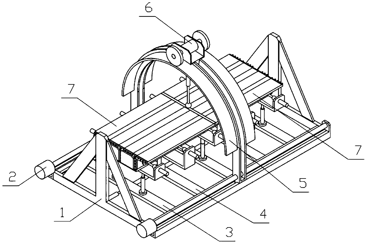
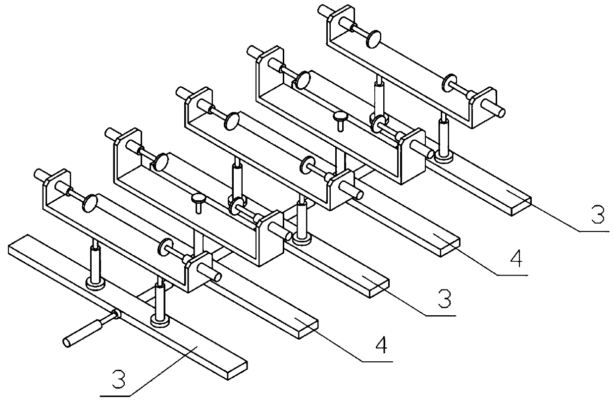
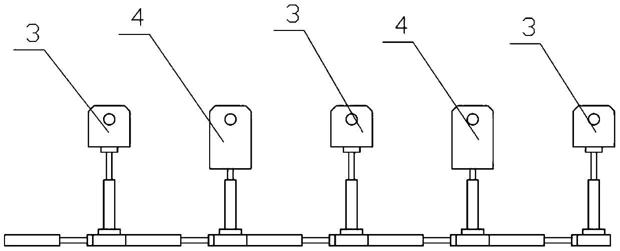
[0037] Combine below Figure 1-14 Description of this embodiment, a bridge combination unit space model experimental device, including device bracket 1, drive motor I2, support mechanism I3, support mechanism II4, angle bracket 5, pressurization mechanism 6 and experimental bridge 7, the drive motor I2 Fixedly connected to the device bracket 1, there are multiple support mechanisms I3, one of which is fixedly connected to the device bracket 1, multiple support mechanisms II4 are provided, and multiple support mechanisms II4 are respectively fixedly connected to multiple support mechanisms Between Ⅰ3, the angle bracket 5 is slidingly connected to the device bracket 1, and the angle bracket 5 is connected to the output shaft of the drive motor I2 through threads, and the angle bracket 5 is slidably connected with a pressurizing mechanism 6, and the pressure mechanism 6 and the angle bracket 5 Engagement transmission, multiple experimental bridges 7 are provided, and the multiple...

specific Embodiment approach 2

[0039] Combine below Figure 1-14 Describe this embodiment, and this embodiment will further explain Embodiment 1. There are two experimental bridges 7, three support mechanisms I3, two support mechanisms II4, and two support mechanisms II4. Between the mechanism I3, two supporting mechanisms II4 and three supporting mechanisms I3 are combined into different clamping modes to clamp the bridge unit.

specific Embodiment approach 3

[0041] Combine below Figure 1-14 Describe this embodiment, this embodiment will further explain the second embodiment, the device bracket 1 includes a support side plate 1-1, a connecting slide rail I1-2 and a connecting slide rail II1-3, and the support side plate 1-1 is set There are two, the connecting slide rail I1-2 is fixedly connected between the two sides of the two supporting side plates 1-1, the outer sides of the two connecting slide rails I1-2 are fixedly connected with the connecting slide rail II1-3, the two The drive motors I2 are fixedly connected to the connecting slide rails I1-2.


PUM


Abstract

The invention relates to a model experiment device, in particular to a bridge combination unit space model experimental device which comprises a device support, a driving motor I, supporting mechanisms I, supporting mechanisms II, an angle support, a pressurizing mechanism and an experimental bridge. A plurality of supporting mechanisms I and a plurality of supporting mechanisms II can be combinedinto different clamping modes to clamp a bridge unit, and different requirements for supporting the bridge unit in an experiment are met; the angle support is driven by the driving motor I to slide on the device support, the pressurizing position of the pressurizing mechanism is adjusted, the pressurizing mechanism is driven by the driving motor II arranged on the pressurizing mechanism to slideon the angle support, and the pressurizing angle of the pressurizing mechanism is adjusted. The experimental bridge is spliced in a shell and beam combination mode, and the number of units is greatlyreduced while the simulation accuracy is guaranteed; and the calculation cost and the convergence difficulty of nonlinear finite element analysis of the concrete box girder are greatly reduced.

Description

technical field [0001] The invention relates to a model experiment device, in particular to a bridge composite unit space model experiment device. Background technique [0002] For example, the publication number CN203275108U is a bridge model static loading device, which includes a base, and the base is provided with at least two supports for placing test samples, and a loading device is also provided in the vertical direction of the base. Compared with the prior art, the utility model has the advantages of: the static loading device specially for the bridge model has a simple structure and low cost; in addition, by setting the guide rails on both sides of the base, the guide rails are set on the support and the pillars. The multi-point measurement of the mechanical properties of the test sample is realized; the pillar adopts the outer rod and the inner rod to realize the lifting of the loading device through the bolt; by setting the displacement gauge on the movable suppor...

Claims


Application Information

Patent Timeline
Patent Type & Authority Applications(China)
IPC IPC(8): G01N3/12
CPCG01N3/12
Inventor 范佳
Owner 范佳
Why Eureka
Try Eureka