
Ground-air short-offset electromagnetic detection system, multi-source emission signal separation method

An electromagnetic detection and short offset technology, applied in the field of geophysical exploration, can solve the problems of unfavorable fine detection of underground anisotropic electrical structures, difficulty in carrying multi-component sensor pods, large pod weight and size, etc., to achieve Effects of economical and flexible multi-component observation, rapid detection and subsurface structure information extraction

Active Publication Date: 2020-11-10
INST OF GEOLOGY & GEOPHYSICS CHINESE ACAD OF SCI
View PDF5 Cites 0 Cited by
  • Summary
  • Abstract
  • Description
  • Claims
  • Application Information

AI Technical Summary

Problems solved by technology

In terms of multi-component observation, the current mainstream solution is to install electromagnetic sensors and other auxiliary sensors in a very highly integrated pod, which will result in a large weight and size of the pod, which can only be carried by manned helicopters. Significant increase in application costs
Although UAV technology has developed rapidly in recent years, it is still difficult for ordinary civilian low-cost UAVs to carry the above-mentioned multi-component sensor pods.
In addition, the existing semi-aerial method uses a single emission source observation method, because this single emission source has only one polarization direction, which is not conducive to the fine detection of underground anisotropic electrical structures

Method used


Image

  • Ground-air short-offset electromagnetic detection system, multi-source emission signal separation method
  • Ground-air short-offset electromagnetic detection system, multi-source emission signal separation method
  • Ground-air short-offset electromagnetic detection system, multi-source emission signal separation method

Examples


Embodiment Construction

[0036] In order to make the purpose, technical solutions and advantages of the present invention clearer, the technical solutions in the embodiments of the present invention will be clearly and completely described below in conjunction with the accompanying drawings. Obviously, the described embodiments are part of the embodiments of the present invention, rather than Full examples. Based on the embodiments of the present invention, all other embodiments obtained by persons of ordinary skill in the art without making creative efforts belong to the protection scope of the present invention.

[0037] The application will be further described in detail below in conjunction with the accompanying drawings and embodiments. It should be understood that the specific embodiments described here are only used to explain related inventions, rather than to limit the invention. It should also be noted that, for the convenience of description, only the parts related to the related invention...


PUM


Abstract

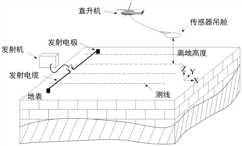
The invention belongs to the field of geophysical exploration, and particularly relates to a ground-air short-offset electromagnetic detection system and a multi-source emission signal separation method. The system comprises a transmitting system and an observation system, wherein the transmitting system comprises one or more transmitting devices which are arranged on the ground and are based on along grounding wire source; the observation system comprises a plurality of observation devices; each observation device comprises flight equipment, a single-component magnetic field sensor and a receiver; the number of the observation devices used for collecting single-component magnetic field data is larger than that of the transmitting devices; a plurality of observation devices carry out flight observation in a set observation area according to a preset formation to obtain a plurality of corresponding groups of observation signals; the set observation area is that the distance from any point to each transmitting device is smaller than N times of the to-be-detected depth, and N is a set value. Economic and flexible multi-component observation is realized, and more possibilities are provided for high-resolution, economic and rapid detection and underground structure information extraction of a deep large ore deposit.

Description

technical field [0001] The invention belongs to the field of geophysical exploration, and in particular relates to a ground-space short-offset electromagnetic detection system and a method for separating multi-source emission signals. Background technique [0002] The electromagnetic method is a geophysical detection method based on the principle of electromagnetic induction. It is based on the difference in physical properties such as the conductivity of the underground medium, and observes the response electromagnetic field (ie, the secondary field) generated by the earth under the excitation of natural or artificial field sources. The spatio-temporal distribution of the secondary field finally realizes the extraction of underground structure information, so it is widely used in the investigation of minerals, groundwater, geothermal and other resources, as well as geological mapping, environmental engineering and other fields. [0003] The traditional electromagnetic detec...

Claims


Application Information

Patent Timeline
Patent Type & Authority Patents(China)
IPC IPC(8): G01V3/08
CPCG01V3/165G01V3/38G01V3/081
Inventor 武欣薛国强周舟
Owner INST OF GEOLOGY & GEOPHYSICS CHINESE ACAD OF SCI
Learn More