Automatic nail loading equipment and automatic nail loading type nail gun system

A nailing type, automatic technology, applied in the direction of nailing tools, U-shaped nailing tools, manufacturing tools, etc., can solve the problems of waste of resources, difficult nailing, nails in the wrong position, etc., to improve the efficiency of nailing , the effect of saving labor costs

Pending Publication Date: 2020-06-12
SHANGHAI BAOYE ELECTROMECHANICAL TECH CO LTD
View PDF0 Cites 5 Cited by
  • Summary
  • Abstract
  • Description
  • Claims
  • Application Information

AI Technical Summary

Problems solved by technology

The whole operation process is labor-intensive, and the nails are often nailed in the wrong place due to fatigue caused by frequent operations, and labor accidents are also prone to occur, resulting in personal injury
[0003] Moreover, the existing pneumatic nail guns or electric nail guns all nail one nail at a time, and the nailing efficiency is low.
In addition, after a row of nails is finished, it is necessary to manually add nails, which is labor-intensive and time-consuming. When the row of nails is broken, it is difficult to add nails, and individual steel nails that are disconnected are often discarded, resulting in a waste of resources.

Method used


Image

  • Automatic nail loading equipment and automatic nail loading type nail gun system
  • Automatic nail loading equipment and automatic nail loading type nail gun system
  • Automatic nail loading equipment and automatic nail loading type nail gun system

Examples


Embodiment Construction

[0022] The specific embodiments of the present invention will be described below with reference to the accompanying drawings and implementations.

[0023] In the following embodiments, the up and down directions are used as reference to describe the directions of the drawings, that is, the left and right directions respectively refer to the left and right directions of the drawings, and the up and down directions respectively refer to the up and down directions of the drawings.

[0024]

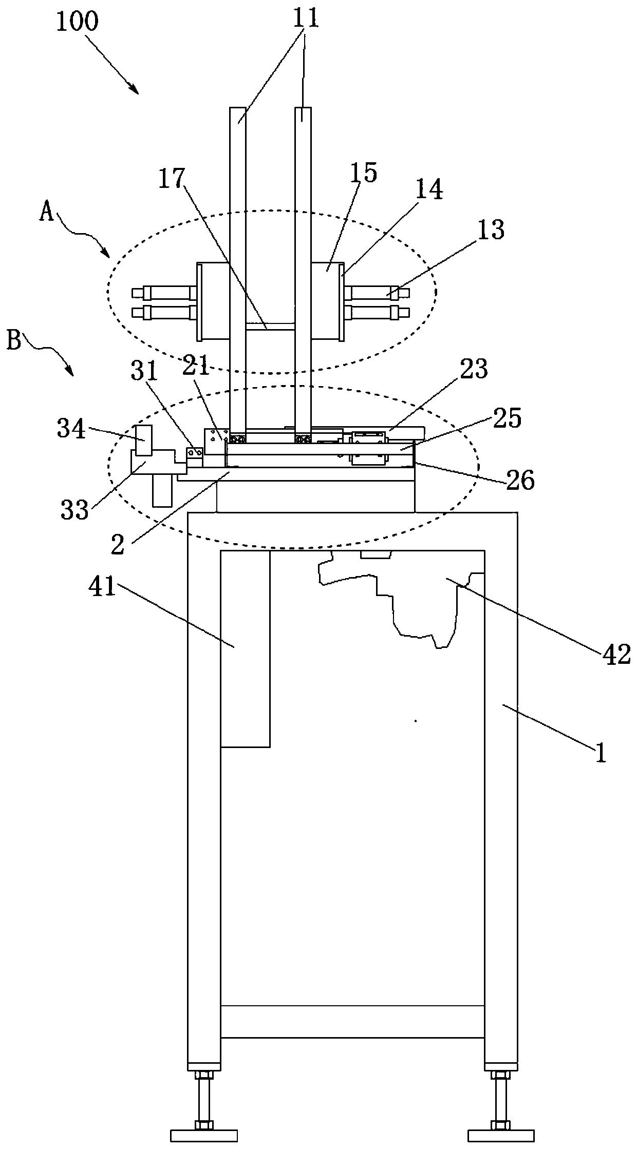
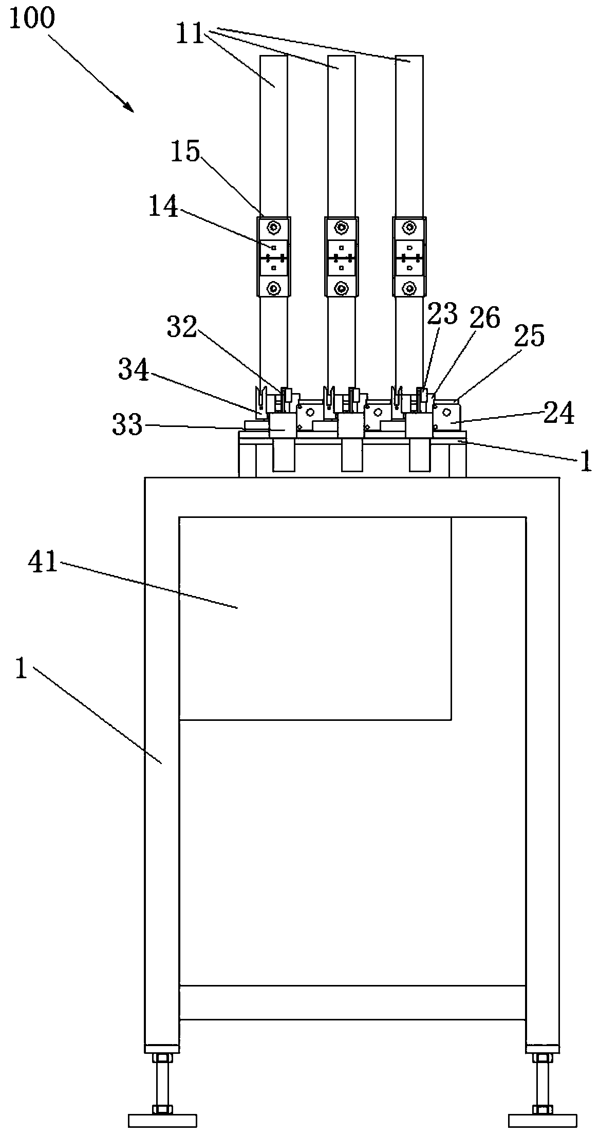
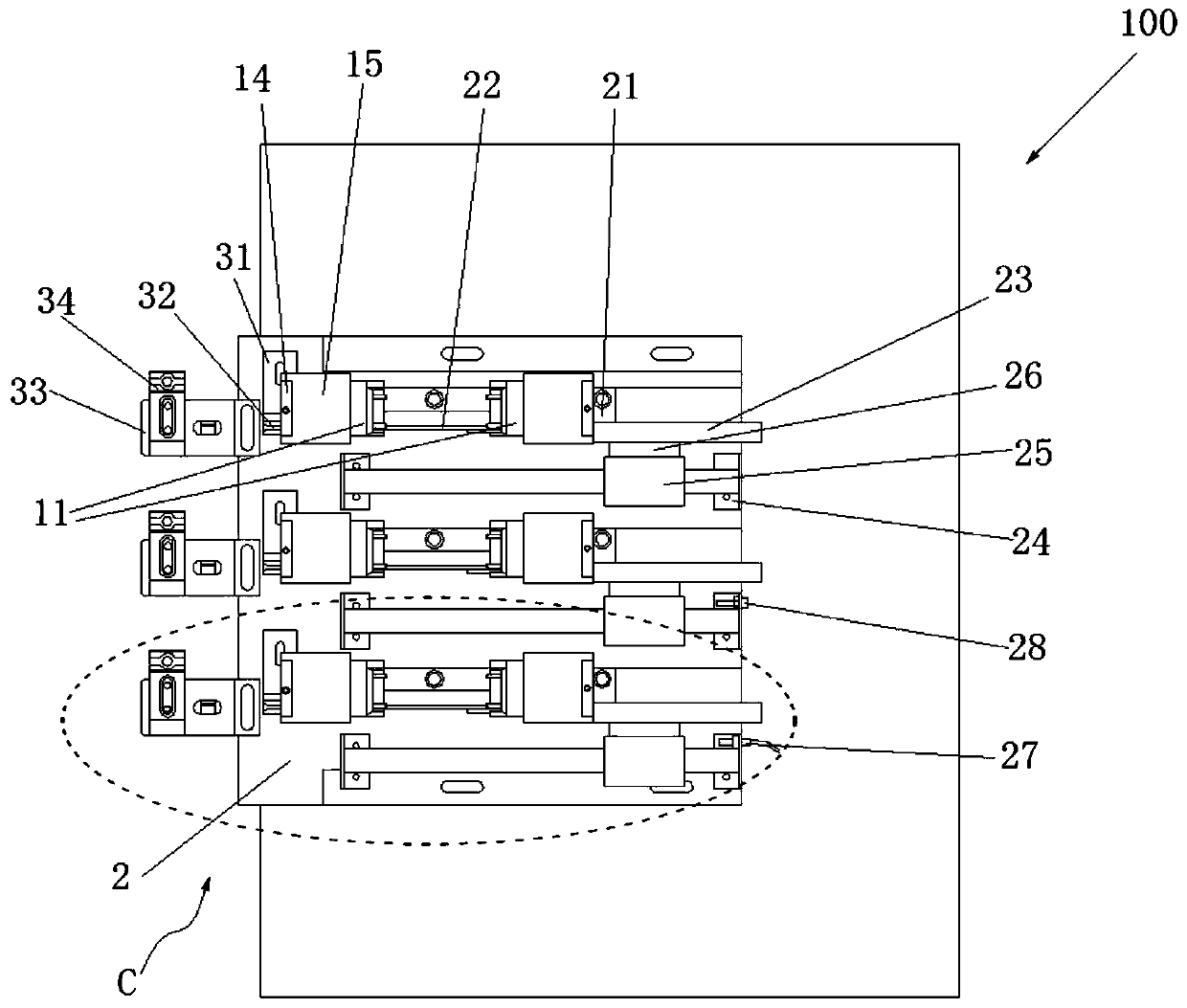
[0025] The automatic nailing device and the automatic nailing type nail gun system provided by the embodiment of the present invention are used to push the nail row into the automatic nailing type nail gun and perform automatic nailing operation.

[0026] The automatic nailing device and the automatic nailing type nail gun system provided in this embodiment include at least one automatic nailing type nail gun and an automatic nailing device 100 for pushing the nail row into the automatic nai...


PUM


Abstract

The invention provides automatic nail loading equipment. The automatic nail loading equipment is used for pushing nail rows into an automatic nail loading type nail gun. The automatic nail loading equipment is characterized in that the automatic nail loading equipment comprises a bottom plate, a nail stacking sliding chute, a plurality of pushing pins, a plurality of pushing pin cylinders, a nailloading rail, a nail pushing rod, a nail pushing cylinder, a joint groove, a displacement detection element and a control module; the nail stacking sliding chute is provided with a first passage stretching in the vertical direction; the plurality of pushing pins are used for controlling the sliding of the nail rows in the first channel; the plurality of pushing pin cylinders are correspondingly connected with the plurality of pushing pins; the nail loading rail is provided with a second channel perpendicular to the first channel; the nail pushing rod is used for pushing the nail rows to move in the length direction of the second channel; The nail pushing cylinder is connected with the nail pushing rod correspondingly through a connecting block; the joint groove is used for being connectedwith the automatic nail loading type nail gun; the displacement detection element is used for detecting the approaching and leaving of the connecting block and outputting corresponding detection electric signals; and the control module is used for control only one nail row to slide into the second channel from the first channel and be pushed into the automatic nail loading type nail gun through the second channel.

Description

technical field [0001] The invention relates to an automatic nailing device, in particular to an automatic nailing device and an automatic nailing type nail gun system. Background technique [0002] A nail gun is a commonly used tool in the field of wood processing such as furniture. Common nail guns are generally operated manually, and the nails are driven into the wood one by one manually. The whole operation process is labor-intensive, and the nails are often driven to wrong positions due to fatigue caused by frequent operations, which is also prone to labor accidents and personal injury. [0003] Moreover, the existing pneumatic nail guns or electric nail guns only drive one nail at a time, and the nailing efficiency is low. In addition, after a row of nails is finished, manual nailing is required, which is labor-intensive and time-consuming. When the nails are broken, it is difficult to add nails. The broken individual steel nails are often discarded, resulting in a wa...

Claims


Application Information

Patent Timeline
Patent Type & Authority Applications(China)
IPC IPC(8): B27F7/13B27F7/02
CPCB27F7/02B27F7/13
Inventor 周春立曹寅张立中
Owner SHANGHAI BAOYE ELECTROMECHANICAL TECH CO LTD
Why Eureka
Try Eureka