PRT suspension vehicle track switching system, control system, track system and driving system
A technology for track conversion and suspension vehicles, which is applied to the elevated railway systems, motor vehicles, railway vehicles and other directions using suspended vehicles, can solve problems such as reducing the working efficiency of suspended rail transit systems, and achieve the effect of improving operating speed and efficiency.
- Summary
- Abstract
- Description
- Claims
- Application Information
AI Technical Summary
Problems solved by technology
Method used
Image
Examples
Embodiment 1
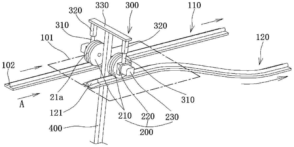
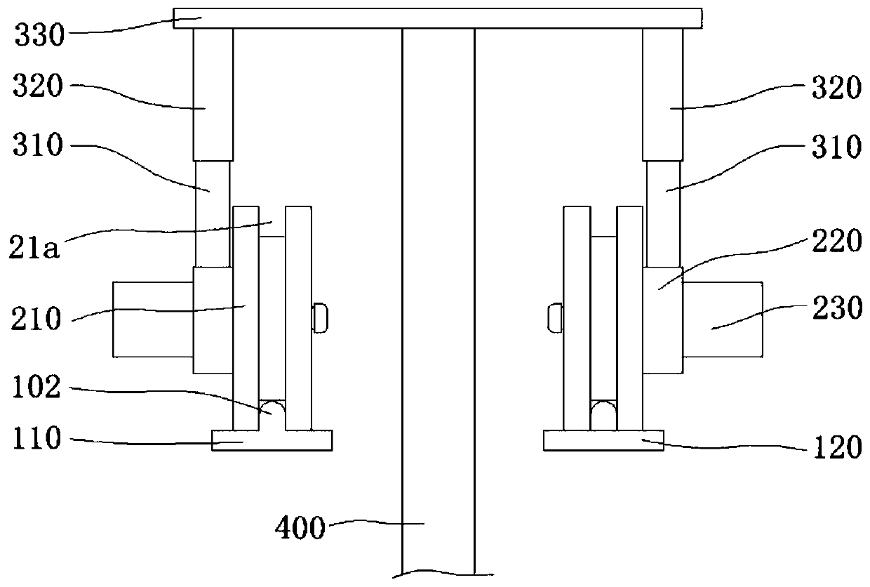
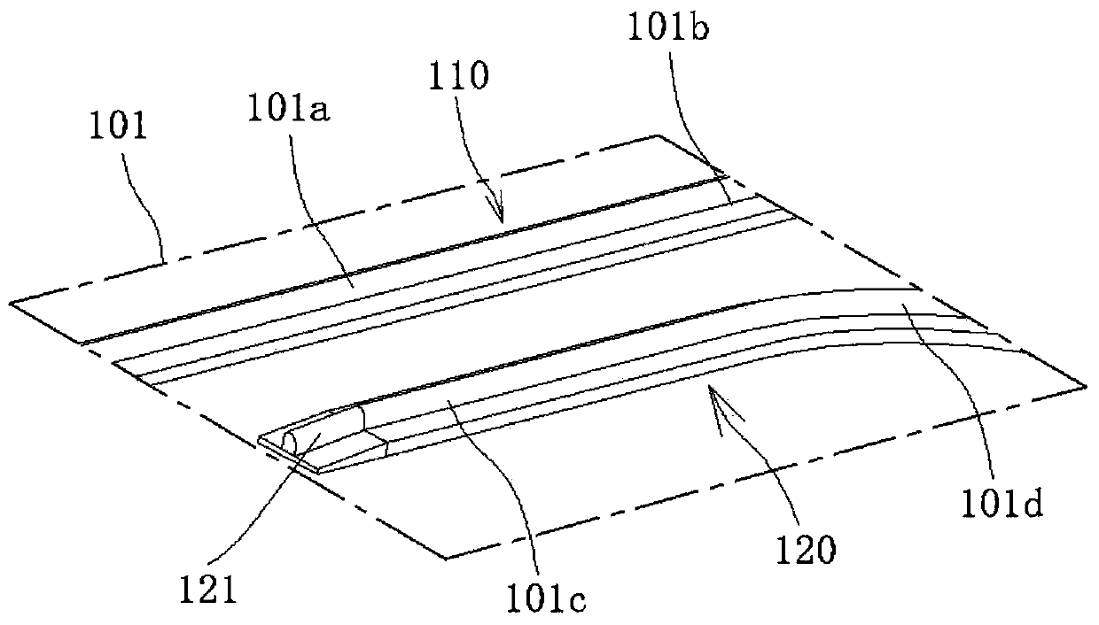
[0056] This embodiment provides a PRT suspension car track conversion system, such as figure 1 As shown, in a preferred implementation of this embodiment, a driving part 200 that can run along a track is provided above the suspension vehicle, and the track includes a running part and a conversion part 101, figure 1 The transition part 101 shown in is a running part; the transition part 101 includes two tracks close to each other, such as figure 1 Shown in the first track 110 and the second track 120 located on the right side of the first track 110, the track conversion system also includes a track changing drive device 300. The first track 110 is the previous track that the suspension vehicle initially runs, and the second track 120 is the subsequent track that the suspension vehicle intends to switch to. When the suspension vehicle does not perform track switching, it always runs on the first track 110.
[0057] The driving part 200 includes two synchronously advancing drivi...
Embodiment 2
[0071] The structural principle of this embodiment is basically the same as that of the first embodiment, except that the structure of the track is different from the structure of the track changing drive device. Specific as Figure 4As shown, in a preferred embodiment, the track is a track with a groove 103, and the track of the running part includes two opposite side walls and a bottom wall 106 connecting the two side walls, for example, the two side walls are respectively For the left side wall 104 and the right side wall 105 , the groove 103 is formed by the area between the two side walls and the bottom wall 106 , and the driving wheel 210 can be locked in the groove 103 and run on the track. In this embodiment, the two driving wheels 210 are connected by a connecting rod 330 , and no telescopic shaft 310 is provided. The first track 110 of the conversion part 101 comprises a left side wall 104 and the bottom wall 106 affixed to the right end of the left side wall 104 wi...
Embodiment 3
[0080] The present invention also provides a suspension vehicle control system, which includes an information input unit, a navigation unit and a track change adjustment unit. The information input unit is at least used to receive the user's destination information, and of course can also receive the departure place, or the input information of the predetermined time and the number of people. The specific input can be input directly on site or remotely via the Internet. The navigation unit receives the user's input information and gives the optimal route information. The specific navigation unit can obtain multiple optional routes according to the destination information, and give the optimal route according to the shortest distance or shortest time. The specific planning method can refer to the existing Planning method for navigation software. The track change adjustment unit receives the optimal path information output by the navigation unit and realizes the track change at...
PUM
 Abstract
Description
Claims
Application Information
 - R&D
- Intellectual Property
- Life Sciences
- Materials
- Tech Scout
- Unparalleled Data Quality
- Higher Quality Content
- 60% Fewer Hallucinations
Browse by: Latest US Patents, China's latest patents, Technical Efficacy Thesaurus, Application Domain, Technology Topic, Popular Technical Reports.
© 2025 PatSnap. All rights reserved.Legal|Privacy policy|Modern Slavery Act Transparency Statement|Sitemap|About US| Contact US: help@patsnap.com


