
Amphibious landing unmanned aerial vehicle

An amphibious and unmanned aerial vehicle technology, applied in the field of unmanned aerial vehicles, can solve problems such as the inability to maintain the balance of unmanned aerial vehicles, affect the flight of unmanned aerial vehicles, and it is not easy to take off quickly.

Active Publication Date: 2020-06-12
广东天浩智能科技有限公司
View PDF7 Cites 5 Cited by
  • Summary
  • Abstract
  • Description
  • Claims
  • Application Information

AI Technical Summary

Problems solved by technology

[0005] In order to solve the above technical problems, the present invention provides an amphibious landing drone that can be used to solve the problem that the existing amphibious landing drone is easy to fall into the water when it lands on the water surface for operations. , and it is easy to shake on the water surface, the contact area with the water surface and the floating block are small, if a large floating block is set, it will easily affect the flight of the drone, and the existing amphibious landing drone is in use When taking off from the water surface, the adsorption force is large, and it is not easy to take off quickly. Moreover, when the drone falls into the water due to failure, it cannot maintain the balance of the drone, and cannot make the side with the floating block in stable contact with the water surface. , so that the problem of the drone falling into the water cannot be avoided

Method used


Image

  • Amphibious landing unmanned aerial vehicle
  • Amphibious landing unmanned aerial vehicle
  • Amphibious landing unmanned aerial vehicle

Examples


Embodiment

[0030] as attached figure 1 to attach Figure 8 Shown:

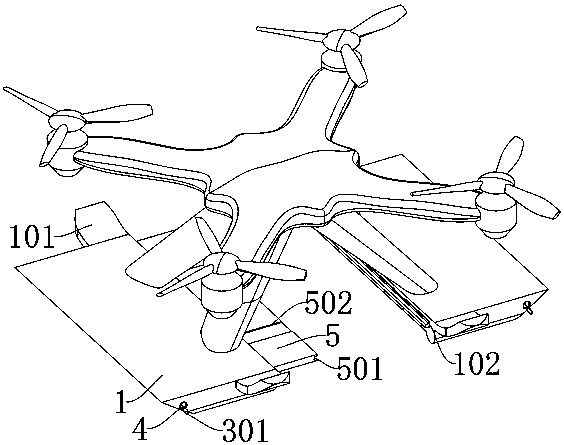
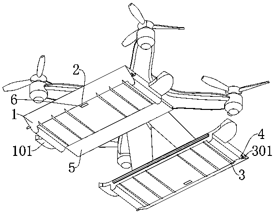
[0031]The present invention provides an unmanned aerial vehicle that can be used for amphibious landing, including: a main body 1, a moving groove 2, a bottom groove 3, a mounting hole 4, a moving plate 5 and a moving block 6; the main body 1 includes an auxiliary part 101, an inner groove 102, guide plate 103; the outside of the main body 1 is a wedge-shaped structure, and the two sides of the main body 1 are provided with arc-shaped auxiliary parts 101; the inside of the main body 1 is provided with a rectangular inner groove 102, and the outer top of the inner groove 102 There is a guide plate 103 with a rectangular structure; the main body 1 is a rectangular plate-shaped structure, and the main body 1 is connected to the bottom of the drone in a corresponding installation manner; the moving slot 2 is set at the middle position inside the inner slot 102, and the moving slot 2 The bottom end is at the bottom of the m...


PUM


Abstract

The invention provides an amphibious landing unmanned aerial vehicle. The amphibious landing unmanned aerial vehicle comprises a main body, a moving groove, a bottom groove, a mounting hole, a movingplate and a moving block, wherein the main body comprises an auxiliary part, an inner groove and a guide plate; the outer side of the main body is of a wedge-shaped structure, and auxiliary pieces ofan arc-shaped structure are arranged on the two sides of the main body; an inner groove of a rectangular structure is formed in the main body, and a guide plate of a rectangular structure is arrangedat the top end of the outer side of the inner groove; the main body is of a rectangular plate-shaped structure, and the main body is connected with the bottom of the unmanned aerial vehicle in a corresponding installation mode; and the bottom groove is formed in the bottom of the main body. When the unmanned aerial vehicle takes off again, the unmanned aerial vehicle can be assisted through the bottom groove, and the situation that the unmanned aerial vehicle cannot take off quickly due to the fact that the bottom of the unmanned aerial vehicle is attracted to the water surface is avoided. Theinterior of the bottom groove is of an inclined structure, and the bottom of the unmanned aerial vehicle can be better separated from the water surface, so that the unmanned aerial vehicle can be conveniently separated from the water surface.

Description

technical field [0001] The invention belongs to the technical field of unmanned aerial vehicles, and more specifically relates to an unmanned aerial vehicle that can be used for amphibious landing. Background technique [0002] Unmanned aerial vehicle, referred to as unmanned aerial vehicle, mainly uses the ground controller to control the flight through wireless sensing technology. It has flexible activities, fast response and low operation requirements, and is widely used. Its main functions are on-site survey, photography, sampling, transportation And so on. [0003] For example, the application number: CN201911160939.3 relates to an amphibious landing UAV, including a body, the outside of the body is fixedly connected to an organic arm, the top of the arm is movably connected to a motor, and the top of the motor is movably connected to a rotating shaft. The end far away from the motor is fixedly connected with a wing, the bottom of the body is fixedly connected with a s...

Claims


Application Information

Patent Timeline
Patent Type & Authority Applications(China)
IPC IPC(8): B64C35/00
CPCB64C35/001B64C35/008
Inventor 李美玲
Owner 广东天浩智能科技有限公司
Learn More