

High-efficiency waste slag digging-conveying integrated device for steelmaking in metallurgical plant
A high-efficiency, metallurgical plant technology, applied in the field of steelmaking, can solve the problem of inconvenient cleaning of waste residues, and achieve the effect of improving the efficiency of slag removal and eliminating the slag removal process.
- Summary
- Abstract
- Description
- Claims
- Application Information
AI Technical Summary
Problems solved by technology
Method used
Image

Examples
Embodiment 1
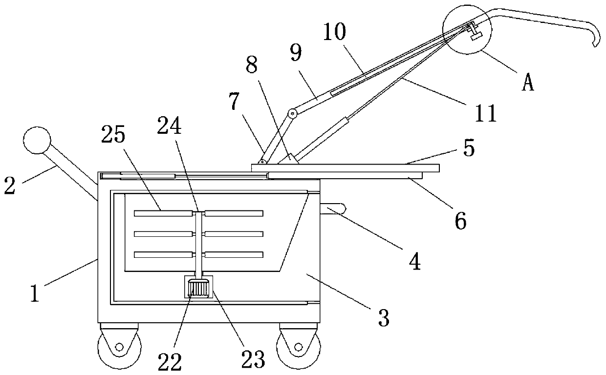
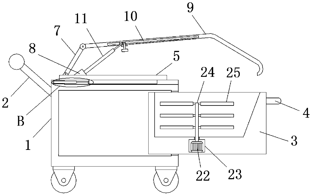
[0033] Embodiment 1: When the device performs slag removal operation inside the steelmaking smelting furnace, first push the device to move to the position of the slag outlet of the smelting furnace, and then pull the pull ring 4 to drive the containing box 3 out , and close to the bottom of the slag outlet, and then start the control switch, so that the first hydraulic rod 11 pushes the slider 12 to slide inside the chute 10, and the slider drives the scraping device to move as a whole, so that the first slag scraper The plate 7 and the second slag removing plate 9 rotate to make the angle between them and the moving plate 5 larger, and then start the second hydraulic rod 16, and the second hydraulic rod 16 pushes the limit bar 6 to slide inside the limit groove 18, The limit bar 6 drives the moving plate 5 to slide on the top of the moving box 1, and drives the slag removal device at the top to move to the inside of the melting furnace as a whole, and then controls the first ...
Embodiment 2
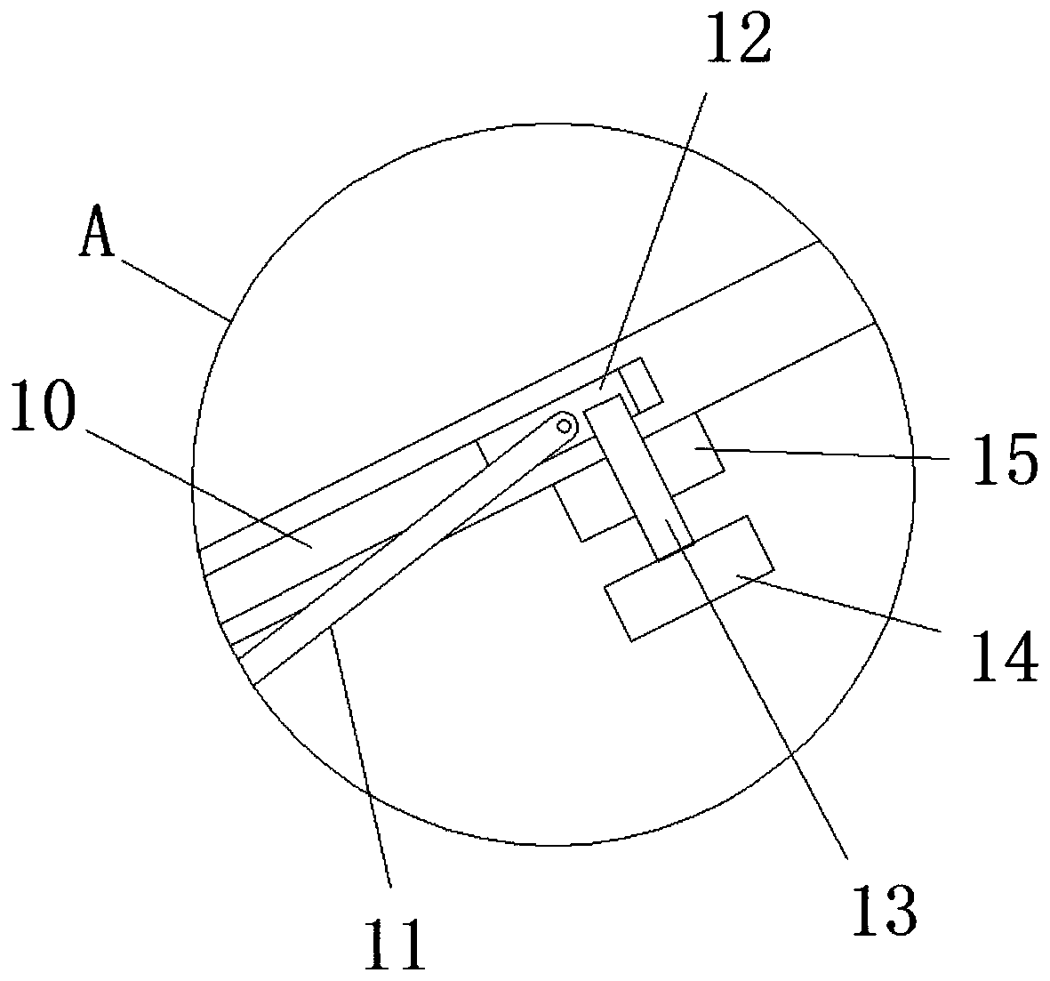
[0034]Embodiment 2: When the first slag removal operation is completed and the second slag removal operation is ready, when the first hydraulic rod 11 pushes the slider 12 to move again, the slider drives the connecting rod 13, and the connecting rod 13 drives the mounting plate 14 and the horizontal plate 19, the horizontal plate 19 moves and drives the scraper 15 to move, and during the movement of the scraper 15, the spring 21 pushes the scraper 15 to slide against the bottom surface of the second slag removal plate 9, so that it can The waste slag adhered to the bottom surface of the second slag removing board 9 is scraped off, thereby improving the slag removing efficiency when the second slag removing board 9 removes slag again.
PUM
 Abstract
Description
Claims
Application Information