Slag blow-removal mechanism

A technology of slag removal machine and hinge mechanism, which is applied in the field of metallurgical equipment, can solve the problems of being unable to adapt to slag removal, and the number of furnaces operated by the gun head, etc., so as to shorten the operation time of slag removal, improve the efficiency of slag removal, and reduce the death of slag removal zone effect

Active Publication Date: 2015-08-12
CISDI ENG CO LTD
View PDF6 Cites 8 Cited by
  • Summary
  • Abstract
  • Description
  • Claims
  • Application Information

AI Technical Summary

Problems solved by technology

[0004] In view of the above-mentioned shortcomings of the prior art, the purpose of the present invention is to provide a non-inserted air blowing and slag removal mechanism, which is used to solve the problem that the existing air blowing and slag removal mechanism cannot adapt to different molten iron level heights and different tipping angles. The problem of slag removal and the small number of furnaces operated by the gun head

Method used


Image

  • Slag blow-removal mechanism
  • Slag blow-removal mechanism
  • Slag blow-removal mechanism

Examples


Embodiment Construction

[0036] The implementation of the present invention will be illustrated by specific specific examples below, and those skilled in the art can easily understand other advantages and effects of the present invention from the contents disclosed in this specification.

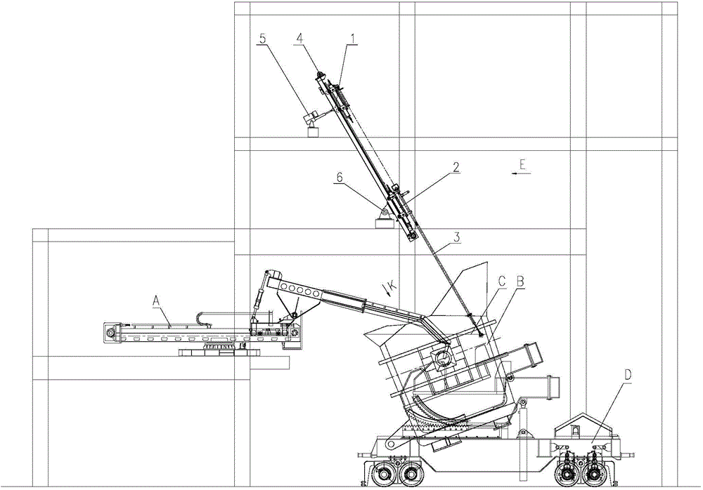
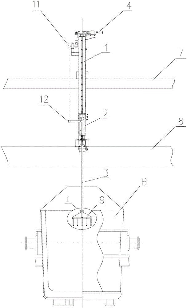
[0037] refer to figure 1 , in the figure, A is the slag removal machine, B is the molten iron tank, C is the slag surface of the molten iron tank, and D is the tipping vehicle of the molten iron tank. After a certain angle, the blowing slag removal mechanism lowers the gun, and the gun head extends above the molten iron level C of the molten iron tank B, blows nitrogen gas, and uses the reaction force of the molten iron level slag on the tank wall to drive the blast furnace slag or desulfurization slag into the The slag removal port of the slag removal machine A is used to remove the blast furnace slag or desulfurization slag in the molten iron tank through the slag removal machine A.

[0038] refer to figure 1 an...


PUM


Abstract

The invention provides a slag blow-removal mechanism comprising a guide rail frame, a lifting trolley, a slag blow-removal spray gun, a lifting transmission device, a tilting device and a hinging mechanism. The guide rail frame is obliquely arranged on the hinging mechanism; under the action of the tilting device, the guide rail frame can rock around a hinge pin of the hinging mechanism; the lifting trolley is slidably connected to the guide rail frame; the slag blow-removal spray gun is fixed to the lifting trolley, and the head of the slag blow-removal spray gun is located above the level of molten iron; the head of the slag blow-removal spray gun is a multi-nozzle arc pipe which is provided with a plurality of blow branch pipes arranged in an arc form; the lifting transmission device is disposed at the top of the guide rail frame and is used for driving the lifting trolley to slide up and down along the guide rail frame. The slag blow-removal mechanism has the advantages such that the mechanism is suitable for removing the slag under different heights of the molten iron and different tilting angles, the area of slag removal in same periods is large, the slag removal area is small, the efficiency is high, the operating time is short, many furnaces can be operated, the structure is simple, and maintenance is convenient.

Description

technical field [0001] The invention belongs to the technical field of metallurgical equipment, in particular to an air blowing and slag removing mechanism for molten iron desulfurization. Background technique [0002] In the process of steelmaking, the desulfurization slag on the surface of the molten iron must be removed from the molten iron after desulfurization treatment, so as to avoid resulfurization during steelmaking. Steelworks are equipped with slag removal machines and air blowing slag removal devices. The air blowing slag removal devices are auxiliary slag removal equipment for hot metal desulfurization. The removal of thin slag can improve the cleaning rate, thereby reducing iron loss and generating huge economic benefits for steel mills. At present, most air blowing and slag removal devices are inserted into the molten iron surface to a certain depth, and the molten iron is turned by blowing air, and the slag on the surface of the molten iron is gathered from ...

Claims


Application Information

Patent Timeline
IPC IPC(8): C21C1/02C21C7/064
Inventor 余杨
Owner CISDI ENG CO LTD
Why Eureka
Try Eureka