Supercharge Your Innovation With Domain-Expert AI Agents!

Hydraulic valve flow velocity detection equipment

A flow rate detection and hydraulic valve technology, applied in the field of hydraulic valves, can solve the problem of difficult to detect the amount of water passing through the valve.

Inactive Publication Date: 2020-06-12
WENZHOU SHUNCHUANG INTELLIGENT TECH CO LTD
View PDF0 Cites 0 Cited by
  • Summary
  • Abstract
  • Description
  • Claims
  • Application Information

AI Technical Summary

Problems solved by technology

[0003] The technical problem to be solved by the present invention is to provide a hydraulic valve flow rate detection device, which overcomes the problem that general valves have strict requirements on the amount of water passing through, and it is relatively difficult to detect the amount of water passing through the valve.

Method used


Image

  • Hydraulic valve flow velocity detection equipment
  • Hydraulic valve flow velocity detection equipment
  • Hydraulic valve flow velocity detection equipment

Examples


Embodiment Construction

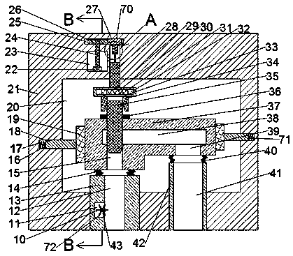
[0018] Combine below Figure 1-4 The present invention is described in detail, wherein, for the convenience of description, the orientations mentioned below are defined as follows: figure 1 The up, down, left, right, front and back directions of the projection relationship itself are the same.

[0019] A hydraulic valve flow rate detection device described in conjunction with accompanying drawings 1-4 includes a detection box 21, a clamping chamber 20 is provided in the detection box 21, a rotating mechanism 70 is provided in the clamping chamber 20, and the The rotating mechanism 70 includes a vertical groove 44 arranged on the upper end wall of the clamping chamber 20, a rotating shaft 28 is rotatably arranged in the vertical groove 44, and a rotating frame 29 is fixedly arranged on the lower end surface of the rotating shaft 28, and the rotating frame 29 is fixed on the lower end surface of the rotating shaft 28. A connecting groove 32 is arranged in the frame 29, and two...


PUM


Abstract

The invention discloses hydraulic valve flow velocity detection equipment. The hydraulic valve flow velocity detection equipment comprises a detection box, and a clamping cavity is formed in the detection box; a rotating mechanism is arranged in the clamping cavity; the rotating mechanism comprises a vertical groove formed in the upper end wall of the clamping cavity; a clamping mechanism is arranged in the clamping cavity; the clamping mechanism comprises two clamping grooves formed in the end wall of the clamping cavity; a clamping rod capable of moving left and right is arranged in the clamping groove; a detection mechanism is arranged in the clamping cavity; the detection mechanism comprises a water outlet pipe fixedly arranged on the lower end wall of the clamping cavity; the device can detect the amount of water capable of passing through the hydraulic valve under the condition that the number of rotating turns of the valve of the hydraulic valve is fixed, when the requirement ismet, sound can be made all the time to remind detection personnel that the valve meets the requirement, and hidden danger existing in later use of the valve can be reduced through detection.

Description

technical field [0001] The invention relates to the field of hydraulic valves, in particular to a hydraulic valve flow rate detection device. Background technique [0002] The hydraulic valve is an automatic component operated by pressure oil. It is controlled by the pressure oil of the pressure distribution valve. It is usually used in combination with an electromagnetic pressure distribution valve. It can be used to remotely control the on-off of oil, gas, and water pipeline systems in hydropower stations. Hydraulic valves There are strict requirements on the amount of water that can pass through the valve after it is rotated. It is generally difficult to detect whether the valve meets the requirements in this respect. If it is not detected, there will be certain hidden dangers. Contents of the invention [0003] The technical problem to be solved by the present invention is to provide a hydraulic valve flow rate detection device, which overcomes the problem that general...

Claims


Application Information

Patent Timeline
IPC IPC(8): G01M13/003G01P5/00
CPCG01M13/003G01P5/00
Inventor 宣佳能
Owner WENZHOU SHUNCHUANG INTELLIGENT TECH CO LTD
Features
  • R&D
  • Intellectual Property
  • Life Sciences
  • Materials
  • Tech Scout
  • Unparalleled Data Quality
  • Higher Quality Content
  • 60% Fewer Hallucinations
Learn More