
Unmanned helicopter-mounted electromagnetic active calibration device, system and method

An unmanned helicopter and calibration technology, applied in radio wave measurement systems, instruments, etc., can solve problems such as affecting calibration accuracy, difficult operation, and high environmental requirements, so as to improve calibration accuracy and meet rapid on-site calibration. effect of demand

Active Publication Date: 2020-06-12
BEIJING INST OF ENVIRONMENTAL FEATURES
View PDF16 Cites 0 Cited by
  • Summary
  • Abstract
  • Description
  • Claims
  • Application Information

AI Technical Summary

Problems solved by technology

Passive calibration usually raises the calibration body or uses a balloon to lift it into the air. On the one hand, the height of the calibration body and the balloon launch have high environmental requirements, and the actual operation in the field is difficult; on the other hand, the bracket and balloon The echo of the object will enter the measurement radar together with the echo of the calibration body, which will affect the calibration accuracy
The active calibration methods developed in recent years are mostly placed on the ground or elevated. If the working environment is not open enough, electromagnetic wave transmission is blocked or multipath effects are formed, the calibration accuracy will still be affected.

Method used


Image

  • Unmanned helicopter-mounted electromagnetic active calibration device, system and method
  • Unmanned helicopter-mounted electromagnetic active calibration device, system and method
  • Unmanned helicopter-mounted electromagnetic active calibration device, system and method

Examples


Embodiment 1

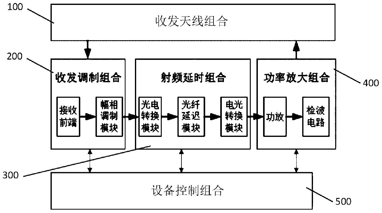
[0044] Such as figure 1 As shown, an unmanned helicopter-borne electromagnetic active calibration device provided by an embodiment of the present invention includes a transceiver antenna combination 100 , a transceiver modulation combination 200 , a radio frequency delay combination 300 , a power amplification combination 400 and a device control combination 500 . Among them, specifically:

[0045] The transceiver antenna combination 100 is used to realize directional reception and directional forwarding of radio frequency signals. The transceiver antenna combination 100 mainly includes a receiving antenna and a transmitting antenna. The receiving antenna is used for directionally receiving the electromagnetic wave signal emitted by the electromagnetic scattering characteristic measurement radar. The transmitting antenna is used for converting the calibration echo signal, that is, the electromagnetic wave processed by the active calibration equipment. The signal is directiona...

Embodiment 2

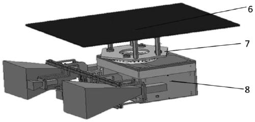
[0055] Such as Figure 2 to Figure 4 As shown, the second embodiment provides an unmanned helicopter-borne electromagnetic active calibration system, including the unmanned helicopter-borne electromagnetic active calibration device 8, the installed structure 7 and the unmanned helicopter as described in any of the above-mentioned embodiments. Helicopter platform. Among them, the unmanned helicopter platform includes the unmanned helicopter body and flight control system. The installed structure 7 mainly completes the structural interconnection between the unmanned helicopter-borne electromagnetic active calibration equipment 8 and the unmanned aerial vehicle platform, that is, the active calibration equipment 8 is mounted on the unmanned helicopter body through the installed structure 7, thereby realizing active calibration. The source calibration equipment can complete the active calibration when the ground is stationary or hovering at high altitude, and it can be applied to...

Embodiment 3

[0063] Embodiment 3 of the present invention provides an unmanned helicopter borne electromagnetic active calibration method, which uses the unmanned helicopter borne electromagnetic active calibration device or unmanned helicopter borne electromagnetic active The calibration system performs calibration, and includes the following steps:

[0064] S1. Install the unmanned helicopter's electromagnetic active calibration equipment on the unmanned helicopter body through the installation structure 7.

[0065] S2. Perform index debugging and calibration on the electromagnetic active calibration equipment carried by the unmanned helicopter.

[0066] Preferably, the performance index debugging and calibration of the active calibration equipment mainly include amplitude adjustment, delay adjustment, detection signal acquisition function debugging, etc.

[0067] Further, the specific steps of amplitude adjustment and detection signal acquisition function debugging in step S2 include: ...


PUM


Abstract

The invention relates to an unmanned helicopter-mounted electromagnetic active calibration device, system and method, the active calibration device comprises a transmit-receive antenna combination, atransmit-receive modulation combination, a radio frequency delay combination, a power amplification combination and a device control combination; the transmit-receive antenna combination is used for realizing directional reception and directional forwarding of radio frequency signals; the transmit-receive modulation combination is used for performing amplitude-phase adjustment on the directionallyreceived radio-frequency signals; the radio frequency delay combination is used for carrying out delay processing on the radio frequency signal after amplitude-phase adjustment; the power amplification combination is used for carrying out power amplification on the radio frequency signal after time delay processing; and the device control combination is used for generating and sending a corresponding working instruction according to an external input instruction and acquiring corresponding feedback information. The electromagnetic scattering characteristic measuring radar on-site rapid calibration method can realize electromagnetic scattering characteristic measuring radar on-site rapid calibration, and furthermore has advantages of high calibration precision and wide application range.

Description

technical field [0001] The invention relates to the technical field of radar measurement, in particular to an unmanned helicopter-borne electromagnetic active calibration device, system and method. Background technique [0002] When carrying out the measurement of electromagnetic scattering characteristics, there are two ways of passive calibration and active calibration. Passive calibration usually raises the calibration body or uses balloons to lift it into the air. On the one hand, the height of the calibration body and the balloon launch have high requirements on the environment, and the actual operation in the field is difficult; on the other hand, the support and balloons The echo of the object will enter the measurement radar together with the echo of the calibration body, which will affect the calibration accuracy. The active calibration methods developed in recent years are mostly placed on the ground or elevated. If the working environment is not open enough, elec...

Claims


Application Information

Patent Timeline
Patent Type & Authority Applications(China)
IPC IPC(8): G01S7/40
CPCG01S7/4052
Inventor 沈小玲孔小琳张云冯孝斌冯雨王晓张达凯刘胤凯苗苗邵景星李熙民
Owner BEIJING INST OF ENVIRONMENTAL FEATURES
Learn More