
Infrared double-station calibration method and calibration system

A calibration and infrared technology, applied to radio wave measurement systems, instruments, etc., can solve problems such as complex and time-consuming processes, poor environmental adaptability, and high visibility requirements, and achieve simple configuration and algorithm, high positioning accuracy, and environmental adaptability Good results

Pending Publication Date: 2022-04-29
HUAZHONG PHOTOELECTRIC TECH INST (CHINA SHIPBUILDING IND CORP THE NO 717 INST)
View PDF0 Cites 0 Cited by
  • Summary
  • Abstract
  • Description
  • Claims
  • Application Information

AI Technical Summary

Problems solved by technology

This method has high requirements on visibility, both stations must be within the line of sight, and the environmental adaptability is poor; manual two-station ranging, the process is complicated and time-consuming

Method used


Image

  • Infrared double-station calibration method and calibration system
  • Infrared double-station calibration method and calibration system
  • Infrared double-station calibration method and calibration system

Examples


Embodiment 1

[0022] A kind of infrared two-station calibration method, see figure 1 , the infrared dual-station calibration method includes: receiving the first satellite positioning signal and the second satellite positioning signal through the first calibration component and the second calibration component respectively, and solving the corresponding first difference position information and the second difference Position information, wherein, the antenna of the first calibration component is installed on the turntable of the main station, the antenna of the second calibration component is installed on the turntable of the auxiliary station, the host of the first calibration component and the second The host of the second calibration component is installed on the system display console; the host of the first calibration component receives the second differential position information calculated by the second calibration component, and solves the problem according to the first differential ...

Embodiment 2

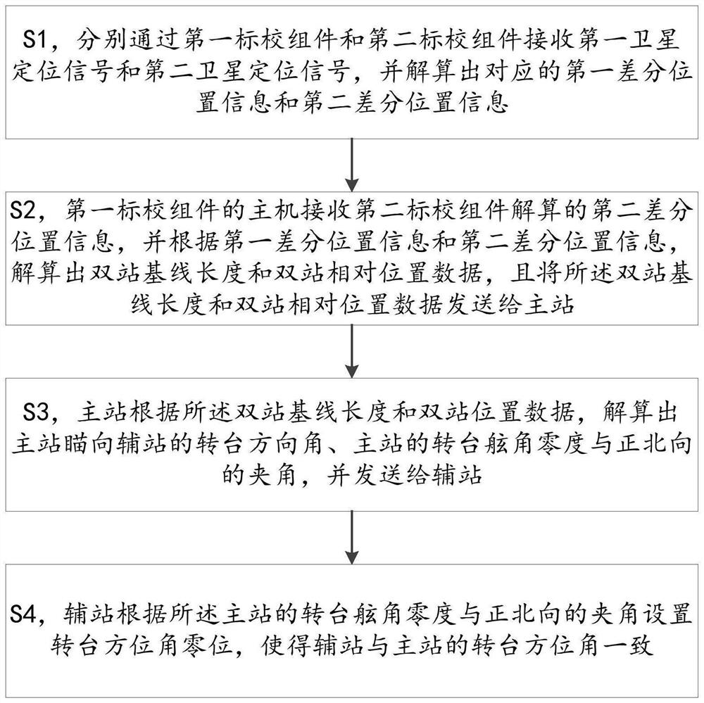
[0034] An infrared dual-station calibration method, the method mainly includes the following steps:

[0035] S1. Receive the first satellite positioning signal and the second satellite positioning signal through the first calibration component and the second calibration component respectively, and calculate the corresponding first differential position information and second differential position information, wherein the first differential position information The antenna of a calibration component is installed on the turntable of the main station, the antenna of the second calibration component is installed on the turntable of the auxiliary station, the host of the first calibration component and the host of the second calibration component are installed on the System display console.

[0036] In the present invention, according to the use environment and use requirements of the infrared detection system, the quick calibration configuration based on the calibration components...

Embodiment 3

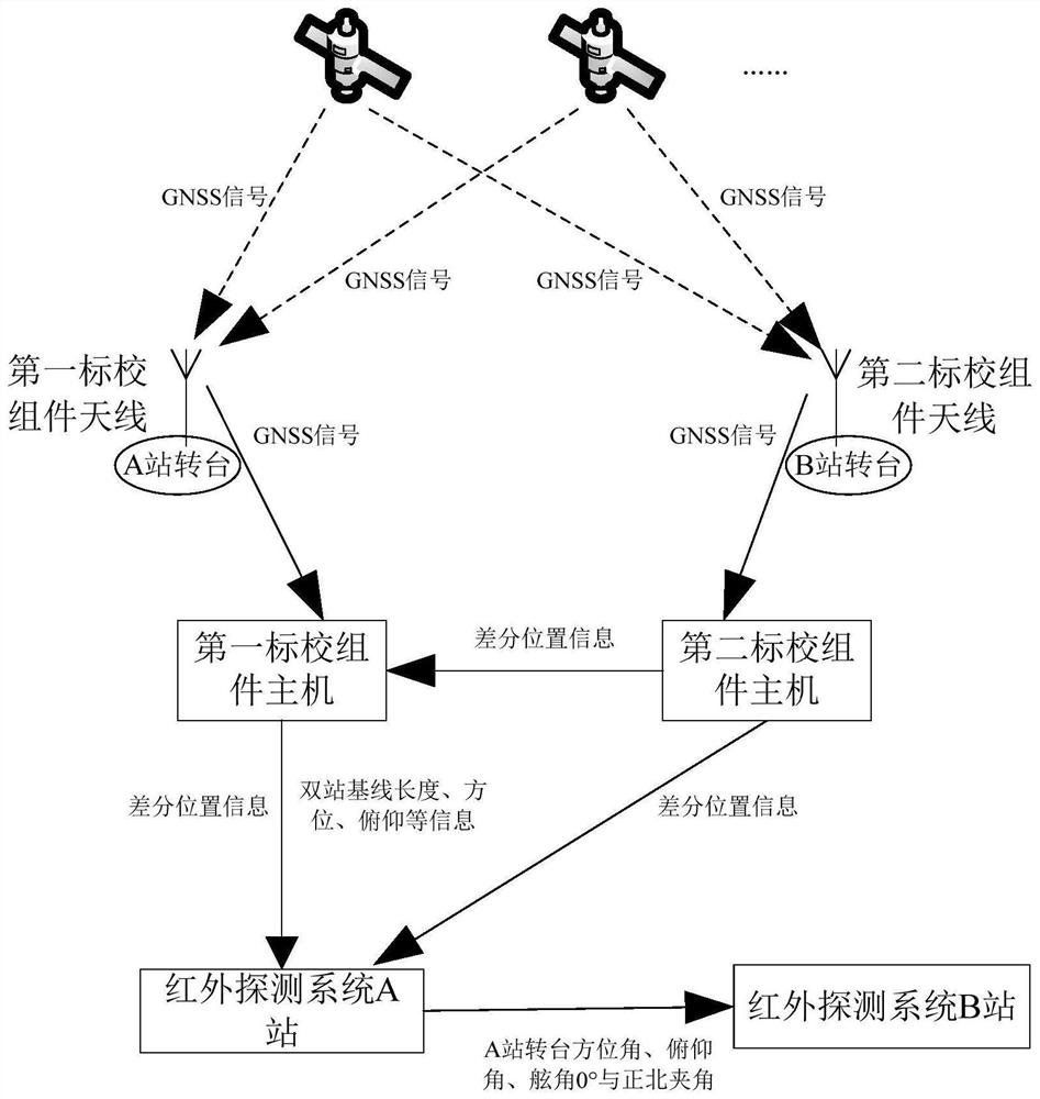
[0067] An infrared dual-station calibration system, see Figure 4 , the infrared dual-station calibration system includes a first calibration assembly 41 and a second calibration assembly 42, the antenna of the first calibration assembly is installed on the turntable of the master station 43, and the antenna of the second calibration assembly is installed on the auxiliary station 44 On the turntable, the host of the first calibration component 41 and the host of the second calibration component 42 are installed on the system display console 45 .

[0068] Wherein, the first calibration component 41 is used to receive the first satellite positioning signal and calculate the corresponding first differential position information; it is also used to receive the second differential position information calculated by the second calibration component 42, And according to the first differential position information and the second differential position information, calculate the bi-stat...


PUM


Abstract

The invention provides an infrared double-station calibration method and calibration system. The calibration method comprises the following steps: respectively calculating differential position information through a first calibration assembly and a second calibration assembly according to a satellite positioning signal; the host of the first calibration assembly calculates the length of a double-station base line and the data of the relative position of the double stations according to the first differential position information and the second differential position information, and sends the data to the master station; the main station calculates a turntable direction angle of the main station aiming at the auxiliary station and an included angle between a turntable side angle zero degree of the main station and the due north direction according to the double-station base line length and the double-station position data, and sends the angle to the auxiliary station; and the auxiliary station sets a turntable azimuth angle zero position according to the included angle between the turntable side angle zero degree of the main station and the due north direction, so that the turntable azimuth angles of the auxiliary station and the main station are consistent. The method has the advantages of being high in positioning precision, good in environmental adaptability and the like, configuration and algorithm implementation are easy, operation is easy and convenient, the user experience is greatly improved, and the requirement for double-station rapid calibration of the infrared detection system is met.

Description

technical field [0001] The invention relates to the field of vehicle-mounted photoelectric equipment, and more specifically, to an infrared dual-station calibration method and a calibration system. Background technique [0002] The infrared detection system needs to detect the distance and relative position of the dual-station infrared sensors. Generally, the dual-station infrared sensors aim at each other to obtain the angular position of the other party's axis angle mechanical zero relative to itself; Manual input to complete the calibration of the distance and relative position of the two stations. This method has high requirements on visibility, both stations must be within the line of sight, and the environmental adaptability is poor; manual two-station ranging, the process is complicated and time-consuming. Therefore, it is necessary to provide a new technical solution to solve the above problems. Contents of the invention [0003] Aiming at the technical problems ...

Claims


Application Information

Patent Timeline
Patent Type & Authority Applications(China)
IPC IPC(8): G01S7/497
CPCG01S7/4972
Inventor 王芙蓉张阳周哲蒙徐迎刚陈亮骆彬张亚唯
Owner HUAZHONG PHOTOELECTRIC TECH INST (CHINA SHIPBUILDING IND CORP THE NO 717 INST)
Learn More