Gear backlash compensation method, system and controller

A backlash compensation and controller technology, applied in belt/chain/gear, transmission parts, mechanical equipment, etc., to improve compensation accuracy and simplify compensation logic

Active Publication Date: 2021-07-16
合肥阳光电动力科技有限公司
View PDF0 Cites 0 Cited by
  • Summary
  • Abstract
  • Description
  • Claims
  • Application Information

AI Technical Summary

Problems solved by technology

When the b-tooth and the C-tooth are attached, there will be a large impact and rebound, which will cause the contact surface of the b-tooth and the C-tooth to repeat many times before they can be stably fitted, that is, there is teeth jitter

Method used


Image

  • Gear backlash compensation method, system and controller
  • Gear backlash compensation method, system and controller
  • Gear backlash compensation method, system and controller

Examples


Embodiment Construction

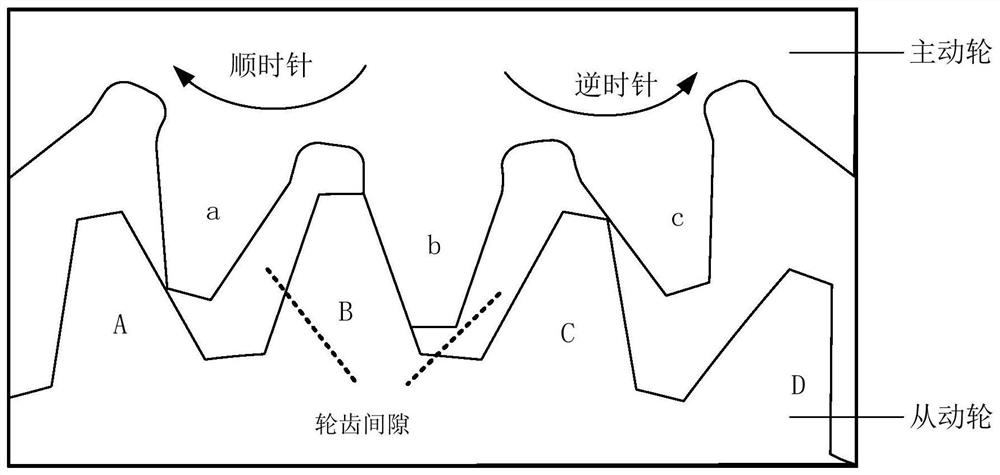
[0043] The structure of the new energy electric vehicle transmission system includes three parts: the drive motor, the gearbox, and the transmission shaft. The three parts are connected by a gear structure. Due to the existence of the gap between the teeth, when the direction of motion of the gear is reversed, it will cross the gap between the teeth and cause gnashing vibration , which in turn leads to the setback of the whole vehicle, poor comfort and driving experience.

[0044]At present, the traditional gear backlash compensation schemes are to perform torque compensation separately for different working conditions where teeth jitter occurs. Accelerator start moment; ②No bite compensation, low speed, step on the accelerator to enter the drive mode; ③No backlash compensation, low speed, release the accelerator to exit the drive mode; ④No backlash compensation, high speed, step on the accelerator, switch from feedback mode Instantaneous in driving mode; ⑤ No gear backlash co...


PUM


Abstract

This application provides a gear backlash compensation method, system and controller. When the program detects that the output torque of the driving wheel is about to change from zero to non-zero or about to reverse, it enters the gear backlash compensation strategy. At this time, the acquisition The relative speed of the driving wheel and the driven wheel, and then compare the relative speed with the relative speed target value, output a bidirectional torque pulse sequence signal, and adjust the output torque of the driving wheel according to the bidirectional torque pulse sequence signal until the relative speed is detected When it is zero, the backlash compensation ends. The solution can eliminate the impact and rebound generated across the gap between the gear teeth during the reverse rotation of the driving gear.

Description

technical field [0001] The invention belongs to the technical field of gear transmission, and in particular relates to a gear tooth clearance compensation method, system and controller. Background technique [0002] In motor control equipment with a gear transmission structure, the inherent characteristics of the gear structure determine that there is a certain redundant space between the teeth that mesh with each other, that is, the gear gap. [0003] See figure 1 , showing a schematic diagram of the tooth meshing process of a gear, assuming figure 1 The upper middle gear is the driving wheel, and the lower gear is the driven wheel. At a certain moment when the driving wheel rotates clockwise, the b tooth of the driving wheel is closely attached to the B tooth of the driven wheel. At this time, there is a large gap between the b tooth and the C tooth. gap. [0004] Due to the existence of the gear tooth gap, when the direction of gear movement changes, for example, the d...

Claims


Application Information

Patent Timeline
Patent Type & Authority Patents(China)
IPC IPC(8): F16H57/12
CPCF16H57/12F16H2057/123
Inventor 刘光辉王辉霍炯于安博
Owner 合肥阳光电动力科技有限公司
Why Eureka
Try Eureka