Refrigeration device and manufacturing method thereof

A technology of a refrigeration device and a manufacturing method, which is applied to household refrigeration devices, defrosting, household appliances, etc., can solve the problems of poor anti-condensation effect, poor contact effect, low thermal conductivity, etc., and achieves the effect of high utilization rate

Inactive Publication Date: 2020-06-16
博西华家用电器有限公司
View PDF6 Cites 0 Cited by
  • Summary
  • Abstract
  • Description
  • Claims
  • Application Information

AI Technical Summary

Problems solved by technology

However, the inventors of the present application discovered during the installation process of the above-mentioned anti-condensation pipe that in order to effectively dissipate the heat of the anti-condensation pipe to the outer wall of the box, etc., the gap between the anti-condensation pipe and the outer wall of the box A heat conduction device is required, but the heat conduction device generally has poor contact with the anti-condensation pipe and the outer wall of the box, resulting in low heat conduction efficiency and poor anti-condensation effect

Method used


Image

  • Refrigeration device and manufacturing method thereof
  • Refrigeration device and manufacturing method thereof
  • Refrigeration device and manufacturing method thereof

Examples


Embodiment 1

[0061] In the first embodiment, a single-door refrigerator is taken as an example to introduce the refrigeration device of the present invention and its manufacturing method in detail.

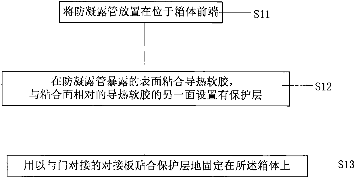
[0062] The following first introduces the production method, and its flow chart is shown in figure 1 shown.

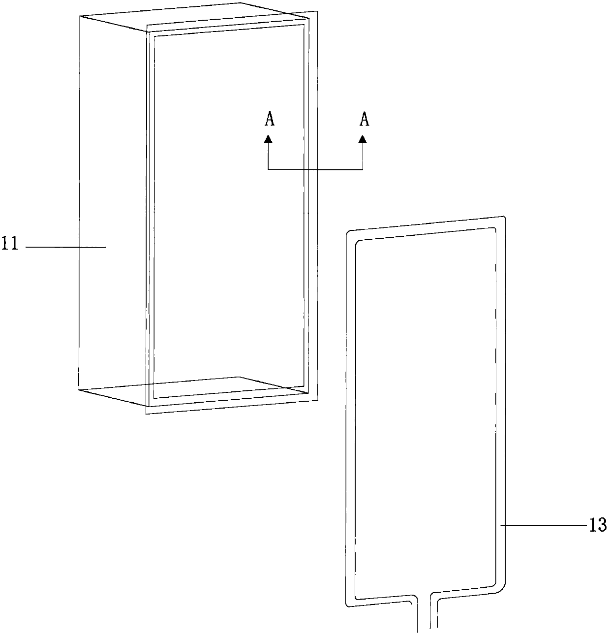
[0063] First, execute step S11, such as figure 2 As shown, the anti-condensation pipe 13 is placed at the front end of the box body 11 .

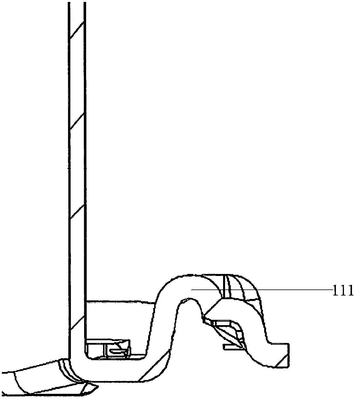
[0064] The above-mentioned front end of the box body 11 refers to the opening of the box body 11, and the opening is subsequently equipped with a door. In the first embodiment, the box body 11 of the single-door refrigerator is a freezer, and the opening of the freezer is the edge of the inner liner in the freezer. In other embodiments, the box body 11 of the single-door refrigerator can also be a cold room. In order to realize the fixing of the anti-condensation pipe 13, the casing 11 has a groove 111 near the edge of the door (the edge of the...

Embodiment 2

[0089] The refrigerator provided in the second embodiment is roughly the same as the refrigerator in the first embodiment, the difference is that, as Figure 9 As shown, butt plate 12' has a U-shaped groove. When step S13 is executed, when the butt plate 12 is fixed on the box body 11 , one side of the U-shaped groove is attached to the protective layer 142 , and the other side is attached to the bottom of the groove 111 .

[0090] The arrangement of the above-mentioned U-shaped groove realizes the automatic engagement of the butt plate 12' on the box body 11, avoids the use of other fixing parts, reduces the cost, and improves the installation efficiency.

Embodiment 3

[0092] The refrigerator provided in this embodiment three is roughly the same as the refrigerator in embodiment one and the refrigerator in embodiment two, the difference is that, refer to Figure 10 The perspective view shown along with the Figure 10 Sectional view of line D-D in Figure 11 As shown, the refrigerator 3 is a refrigerator with two doors. At this time, the docking plate 12" is a middle partition separating the two doors. Condensation pipe 13.

[0093] It should be noted that, in order to visually display the positional relationship between the butt plate 12" (intermediate partition) and the box body 11 and the anti-condensation pipe 13, Figure 10 The butt plate 12" in the frame adopts a perspective effect.

[0094] It can be understood that, in other embodiments, the refrigerator can also have three or more doors, and a middle partition is used between two adjacent doors to divide.


PUM


Abstract

A refrigeration device comprises a box body and at least one door which is connected to the box body, and further comprises a condensation prevention pipe and a heat conduction device. The box body comprises a butt joint plate. The butt joint plate is used for being connected with the at least one door in a butt joint mode when the at least one door is closed. The condensation prevention pipe is located on the inner side of the butt joint plate. The heat conduction device is suitable for guiding the heat of the condensation prevention pipe to the butt joint plate, and comprises a heat conduction soft rubber and a protective layer which is located between the heat conduction soft rubber and the butt joint plate. The invention further provides a manufacturing method of the refrigeration device. By the adoption of the technical scheme, the condensation prevention effect of the refrigeration device can be improved.

Description

technical field [0001] The invention relates to the technical field of refrigeration, in particular to a refrigeration device and a manufacturing method thereof. Background technique [0002] Refrigeration device, in the process of use, the heat in it will inevitably spread to the outside of the box through the heat insulation layer, and the hot air from the outside will meet the outer wall of the box with a lower temperature (such as the butt plate at the door opening and closing) ), it is easy to condense into dew near the door frame. In order to avoid the above-mentioned condensation problem, the existing refrigeration device generally arranges an anti-condensation pipe between the inner tank and the outer wall of the box to heat the outer wall of the box. However, the inventors of the present application discovered during the installation process of the above-mentioned anti-condensation pipe that in order to effectively dissipate the heat of the anti-condensation pipe t...

Claims


Application Information

Patent Timeline
Patent Type & Authority Applications(China)
IPC IPC(8): F25D21/04
Inventor 黄也贵吴强李慧解荣凯
Owner 博西华家用电器有限公司
Why Eureka
Try Eureka