

Aircraft power supply system communication architecture
A technology of aircraft power supply system and communication, which is applied in the field of aircraft power system communication architecture, and can solve problems such as increasing hardware costs, increasing product volume and weight, and reducing reliability
- Summary
- Abstract
- Description
- Claims
- Application Information
AI Technical Summary
Problems solved by technology
Method used
Image

Examples
Embodiment 1
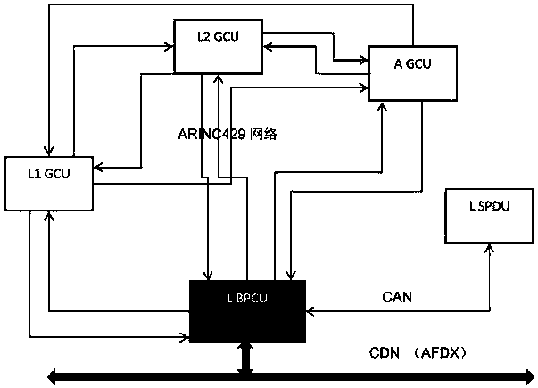
[0031] Architecture design of two-level communication system based on AFDX and CAN
[0032] figure 2 The two-level communication system architecture design based on AFDX and CAN proposed for this patent involves the following devices:
[0033] -2 BPCUs (Bus Bar Power Controllers), 1 each on the left and right
[0034] -4 sets of GCU (Generator Controller), 2 sets on the left and right;
[0035] -1 A GCU, divided into the left network
[0036] -1 RAT GCU, divided into the right network
[0037] -2 SPDUs (Secondary Power Distribution Units), 1 each on the left and right
[0038] - 4 G RPDUs (Remote Power Distribution Units), 2 on the left and right, as gateways to the RPDU subnet
[0039] - 12 sets of S RPDUs, 6 sets on the left and right, as the equipment of the RPDU subnet
[0040] This patent divides the above equipment into 6 subnets, which are:
[0041] -Subnet 1: L BPCU, L1 GCU, L2 GCU, A GCU and L SPDU, where L BPCU acts as the gateway of the subnet and communicat...
Embodiment 2
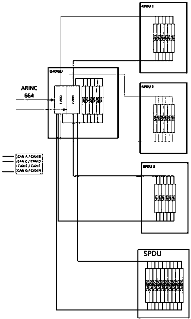
[0050] The two-level communication system architecture design based on AFDX and CAN proposed in this patent
[0051] Figure 4 The two-level communication system architecture design based on AFDX and CAN proposed for this patent involves the following devices:
[0052] -2 BPCUs (Bus Bar Power Controllers), 1 each on the left and right
[0053] -4 sets of GCU (Generator Controller), 2 sets on the left and right;
[0054] -1 A GCU, divided into the left network
[0055] -1 RAT GCU, divided into the right network
[0056] -2 SPDUs (Secondary Power Distribution Units), 1 each on the left and right
[0057] - 4 G RPDUs (Remote Power Distribution Units), 2 on the left and right, as gateways to the RPDU subnet
[0058] - 12 sets of S RPDUs, 6 sets on the left and right, as the equipment of the RPDU subnet
[0059] This patent divides the above equipment into 6 subnets, which are:
[0060] -Subnet 1: L BPCU, L1 GCU, L2 GCU, A GCU and L SPDU, where L BPCU acts as the gateway of ...
Embodiment 3
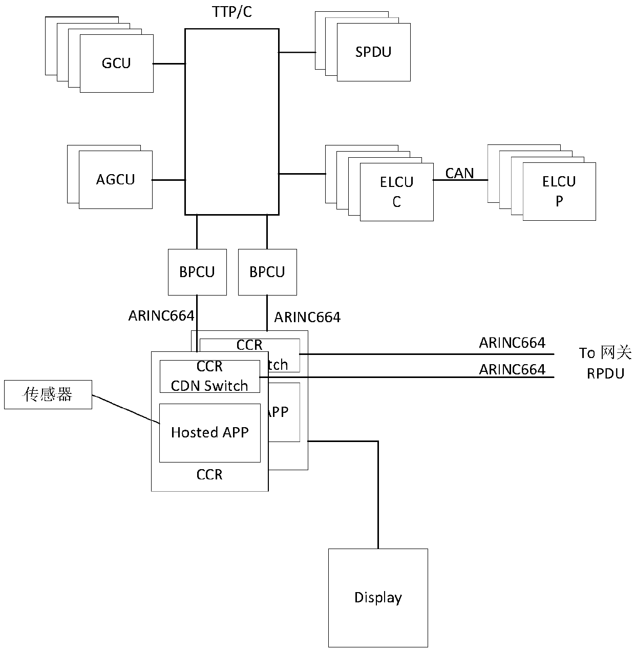
[0071] 2. The two-level communication system architecture design based on AFDX and CAN proposed in this patent
[0072] Figure 7 The two-level communication system architecture design based on AFDX and CAN proposed for this patent involves the following devices:
[0073] - 2 BPCUs (Bus Power Controllers), 1 on the left and 1 on the left
[0074] - 4 GCUs (generator controllers), 2 on the left and right;
[0075] - 1 A GCU, divided into the left network
[0076] - 1 RAT GCU, divided into the right network
[0077] - 2 SPDUs (Secondary Power Distribution Units), 1 each on the left and right
[0078] - 4 sets of G RPDU (Remote Power Distribution Unit), 2 sets on the left and right, as the gateway of the RPDU subnet
[0079] - 12 sets of S RPDUs, 6 sets on the left and right, as the equipment of the RPDU subnet
[0080] This patent divides the above-mentioned equipment into 4 subnets centered on G RPDU, which are:
[0081] - Subnet L1 G RPDU and R2 G RPDU with SPDU: L1 G R...
PUM
 Abstract
Description
Claims
Application Information